I do have pulses, offset a typical amount from one another. I can post a pic, but I don't think it would be needed at this point. Placed my order with fairchild for the 75339's already, should see them tuesday.
I wanted to try a different fet until the replacements arrived, but only having 70n06 didn't prove out very good. The signal on the gates was very ugly. Removed those before I could cause anymore damage. These would work at low gain, if I adjusted to gain up any amount the output would look like noise and the xfrmer would squeal.
I wanted to try a different fet until the replacements arrived, but only having 70n06 didn't prove out very good. The signal on the gates was very ugly. Removed those before I could cause anymore damage. These would work at low gain, if I adjusted to gain up any amount the output would look like noise and the xfrmer would squeal.
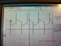
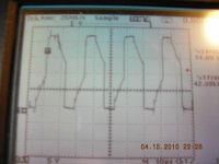
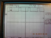
Replaced the blown PS fets and I have the same result. Once the gain is adjusted up (very little) the xfrmer squeals and the signal becomes noisy. I also get 2.5Vdc on the output. Attached are the waveforms on pins 8 and 11of the 494. The first is with gain adjusted all the way down, the next is failure mode. It seems the amp doesn't turn on until gain is adjusted up. I have no output signal until then.
The LM393 voltages don't change in the different states.
Any ideas?
The LM393 voltages don't change in the different states.
Any ideas?
Attachments
The drive signals look close to what I'd expect.The following image is an MTX amp.
http://www.bcae1.com/temp/mtxamp01.swf
What happens if you leave the gain at the minimum but increase the input signal level to get the same overall output voltage?
Is it possible that you have an open shield ground on the RCA jacks?
http://www.bcae1.com/temp/mtxamp01.swf
What happens if you leave the gain at the minimum but increase the input signal level to get the same overall output voltage?
Is it possible that you have an open shield ground on the RCA jacks?
I am using a cd changer for my source, no adjustment. I would have to switch over to the ipuke. That could lead to other problems though.
The ground measures fine, I get roughly 1k to the supply gnd. The rca jacks are physically loose, the crimp portion.
I will give the ipuke a try.
The ground measures fine, I get roughly 1k to the supply gnd. The rca jacks are physically loose, the crimp portion.
I will give the ipuke a try.
I used the exact replacement IRFP240.
I noticed before calling it quits last night the gate signals are different. The fets on the neg. rail have a square wave riding on a neg. dc level. The fets on the pos rail show ref at zero and a messed up sine wave. Can't remember what I used for my scope reference point though.
I noticed before calling it quits last night the gate signals are different. The fets on the neg. rail have a square wave riding on a neg. dc level. The fets on the pos rail show ref at zero and a messed up sine wave. Can't remember what I used for my scope reference point though.
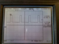
Here are the gate signals. The low side (waveform b)seems ok, is the high side (waveform a) what you expect? This is without any outputs fets in place.
With the outputs in place the high side waveform doesn't look like this at all.
With the outputs in place the high side waveform doesn't look like this at all.
Attachments

I think those transistors run hot normally.
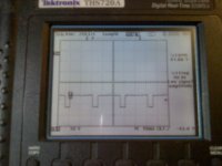
Using both channels of the scope, touch both probes to the negative rail and align the traces directly on top of each other.
With the scope set to trigger in channel 1, touch the ch1 probe to the gate and the ch2 probe to the source. Post the photos from both the high side and the low side FETs.
Using both channels of the scope, touch both probes to the negative rail and align the traces directly on top of each other.
With the scope set to trigger in channel 1, touch the ch1 probe to the gate and the ch2 probe to the source. Post the photos from both the high side and the low side FETs.
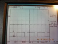
That looks right. The drive waveforms have an amplitude of ~10v above the source and the rising and falling edges appear to be square (although that's not really definitive at 40Hz).
Did 2 of the original outputs survive?
If so, install one in the high side and one in the low side to see if the amp produce audio at higher output that it did before.
Did 2 of the original outputs survive?
If so, install one in the high side and one in the low side to see if the amp produce audio at higher output that it did before.
- Status
- This old topic is closed. If you want to reopen this topic, contact a moderator using the "Report Post" button.
- Home
- General Interest
- Car Audio
- MTX 421D supply issue