Hello, first post...
I have a MTX Thunder 895 amp that has two burned resistors and a burned FET... I am not too familiar with electronics repairs, further than soldering and pretty much computer repairs... Not much clue how to test outputs and only equipment would be a multi-meter...
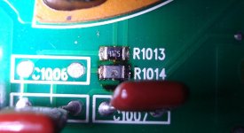
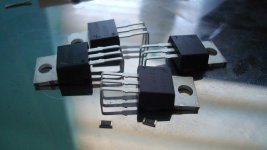
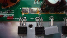
The bad resistors are #s R1013 and R1014, the FETs are #s FET1001 and FET1002... The values on the resistors appear to be 4725, but I am not sure as both are burned, both circular but ironically one outward and on inward... The FETs are the 75339P / N2 18 type, not sure if these can be swapped for better ones... Ive read up a few posts and know to make sure they are clamped down when powering on the amp as well as using a small fuse for testing...")
While driving, an aluminum soda bottle rolled under the seat where the amp is installed and I didnt notice... At one point the audio stopped, but after powering off and on the radio the sound returned... An hour later driving home, I kept smelling like what was overheated brakes and about 5min later the sound just fizzled out from near full volume to 0 in about 3-4 seconds... After trying one last time at home, I would get very faint sound when the audio was maxed on the head unit, didnt check which channels played though...
I wouldnt mind contacting Mitek or whoever it is that does the repairs for the parts, but I cannot send it in as money is drier than dry for the next few months and Im tired of listening to my exhaust... :-(
Any help anyone could provide I would be very grateful...
Thanks.
-jbeckford1
I have a MTX Thunder 895 amp that has two burned resistors and a burned FET... I am not too familiar with electronics repairs, further than soldering and pretty much computer repairs... Not much clue how to test outputs and only equipment would be a multi-meter...
The bad resistors are #s R1013 and R1014, the FETs are #s FET1001 and FET1002... The values on the resistors appear to be 4725, but I am not sure as both are burned, both circular but ironically one outward and on inward... The FETs are the 75339P / N2 18 type, not sure if these can be swapped for better ones... Ive read up a few posts and know to make sure they are clamped down when powering on the amp as well as using a small fuse for testing...
While driving, an aluminum soda bottle rolled under the seat where the amp is installed and I didnt notice... At one point the audio stopped, but after powering off and on the radio the sound returned... An hour later driving home, I kept smelling like what was overheated brakes and about 5min later the sound just fizzled out from near full volume to 0 in about 3-4 seconds... After trying one last time at home, I would get very faint sound when the audio was maxed on the head unit, didnt check which channels played though...
I wouldnt mind contacting Mitek or whoever it is that does the repairs for the parts, but I cannot send it in as money is drier than dry for the next few months and Im tired of listening to my exhaust... :-(
Any help anyone could provide I would be very grateful...
Thanks.
-jbeckford1
Attachments
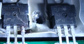
The FETs are HUF75339Ps. They are good FETs. Go back with the same part.
HUF75339P3 Fairchild Semiconductor MOSFETs
The top resistor is likely a 47.5 (47R5). I don't know what the other one is. If you could post a photo showing a slightly wider area than photo #2, it may help determining how they're being used.
HUF75339P3 Fairchild Semiconductor MOSFETs
The top resistor is likely a 47.5 (47R5). I don't know what the other one is. If you could post a photo showing a slightly wider area than photo #2, it may help determining how they're being used.
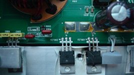
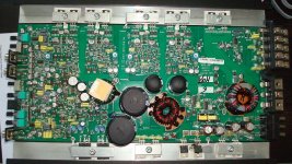
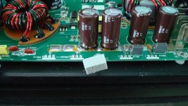
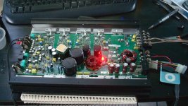
Photo 1 is a slightly wider and photo 4 is the whole board, the location of the burned components in photo 4 is the bottom right about 1/4 way in... The components are barely an inch apart and seem to be the only things a affected...
Thanks for your response and time. Let me know if pic 1 does not suffice...
Also found a handy SMD resistor code calculator: http://www.hobby-hour.com/electronics/smdcalc.php
-jbeckford1
Thanks for your response and time. Let me know if pic 1 does not suffice...
Also found a handy SMD resistor code calculator: http://www.hobby-hour.com/electronics/smdcalc.php
-jbeckford1
Last edited:
Does one end of R1013 go to the first leg of two of the power supply FETs?
Does one end of R1014 go to the first leg of the other two power supply FETs?
Does the other end of each of the resistors connect to the two small yellow transformers (or to one of the yellow transformers)?
If so, both resistors are likely 47.5 ohms.
Does one end of R1014 go to the first leg of the other two power supply FETs?
Does the other end of each of the resistors connect to the two small yellow transformers (or to one of the yellow transformers)?
If so, both resistors are likely 47.5 ohms.
Ok, here goes. For the FETs, I am assuming the square copper seat is for pin1, if so, then pin3 goes to ground/earth. I cannot follow the trace on the right side of the resistors but both show 0-ohm continuity to ground. The left side of R1013 is in parallel with the 1st red cap below the pair (C1005) and goes to pin1 of FET1001. R1014 is the same but C1007 parallel to FET1002. Pin2 of the FETs go to 12v/B+.
Not to get ahead of myself, but should I also be replacing the insulators below the FETs since I had to lift the board to follow the traces on the other side..??
Thanks so much PB.
Not to get ahead of myself, but should I also be replacing the insulators below the FETs since I had to lift the board to follow the traces on the other side..??
Thanks so much PB.
Thanks so much for everything, really. So on my list of things to get will be 5 FETs (going to replace all 4 since they all connect to B+). 3 - 47.5ohm resistors, an insulator pad and thermal compound. What would u say about replacing the caps though they are not bulging, but to get some premiums w/ low ESR? Also, as far as the speaker/power connections should I leave them w/ the raw wire or should I use spade/ring terminals?
Thanks Midnight, but I found them with the link PB provided... Maybe I a little tired from looking so long, but the thermal pads I seem to have found are 1mm thick..!! Those seems to be the gel type which I think are too soft and would short the FETs, am I correct..?? I need the cloth type insulators, along with the thermal compound right..??
The pads I refer to are listed here. The Ferrishield, which is also the only one in stock, does not list whether the pads are electrically insulating, the other pads are not... Are there any other sources for electrically insulated thermal pads..?? Maybe Im just lost...
PB you have been a great help...
Thanks.
-jbeckford1
If you need insulators, I'd recommend mica (and heatsink compound).
4673 Keystone Electronics Mounting Hardware
The compound has to be applied both between the transistor/insulator and between the insulator/sink.
4673 Keystone Electronics Mounting Hardware
The compound has to be applied both between the transistor/insulator and between the insulator/sink.
If you plan on doing more repairs in the future, the following material makes a good insulator.
Polyimide Kapton MT Film .002" x 5.5?W x 72?L insulator - eBay (item 380204710092 end time Apr-08-10 10:14:21 PDT)
Polyimide Kapton MT Film .002" x 5.5?W x 72?L insulator - eBay (item 380204710092 end time Apr-08-10 10:14:21 PDT)
Hmmmmm...
Grrrr... Just completed the order, and forgot the thermal grease..!! I think radio shack has some thermal compound though, so I'll look into that...
But thanks so much for everything... If all goes well, I will try to remember to come back and post, lol...
-jbeckford1
Grrrr... Just completed the order, and forgot the thermal grease..!! I think radio shack has some thermal compound though, so I'll look into that...
But thanks so much for everything... If all goes well, I will try to remember to come back and post, lol...
-jbeckford1
She lives...
So watched the mailman today and he dropped off a single small carboard box... it was time..!!
Got some heatsink compound from RS, and got to work... Took me a while though since it was my first time and I wanted to make sure I didnt toast anything soldering, or upon first power up... I was successful and as a matter of fact, seems to be playing louder than before... The only issue was when the 3rd or 4th main RCA were connected, the amp light would pulsate along with the audio output to whichever channel was just plugged in... I lowered the gain on all channels and that seemed to have stopped it, but I did smell something, not sure if one of the FETs are toasted... I work tomorrow and installed it kinda late, so I just left it... Thanks again so much to those who help on the site, but especially PB... Please enjoy the pics...
So watched the mailman today and he dropped off a single small carboard box...
it was time..!!Got some heatsink compound from RS, and got to work... Took me a while though since it was my first time and I wanted to make sure I didnt toast anything soldering, or upon first power up... I was successful and as a matter of fact, seems to be playing louder than before... The only issue was when the 3rd or 4th main RCA were connected, the amp light would pulsate along with the audio output to whichever channel was just plugged in... I lowered the gain on all channels and that seemed to have stopped it, but I did smell something, not sure if one of the FETs are toasted... I work tomorrow and installed it kinda late, so I just left it... Thanks again so much to those who help on the site, but especially PB... Please enjoy the pics...
Attachments
Luckily came across this post because I have the exact same issue. I didn't even notice the resistors until I read this post and then saw mine.
I am hoping to repair mine but I do not know which resistors to order. Can you share with me the part number that you used? I appreciate any help you can give.
Thanks
I am hoping to repair mine but I do not know which resistors to order. Can you share with me the part number that you used? I appreciate any help you can give.
Thanks
- Status
- This old topic is closed. If you want to reopen this topic, contact a moderator using the "Report Post" button.
- Home
- General Interest
- Car Audio
- MTX Thunder 895 repair