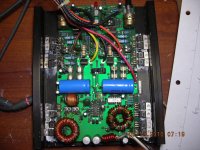
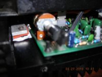
It also appears that you have a blown channel < the one missing the fuses and the blown cap near the outputs >
By my experience you will also have bad drivers D40D8 and or D41D8 These can be a bit tough to find nowadays. GE stop making these a very long time ago. The power supply looks Ok visually but a ohm meter check will tell all about those devices.
The Rfp18N10 are regulator pass elements providing the 18 volt rails to the front end IIRC I would check the zener diodes feeding them. Also touch up the solder on the four power diodes on the board they run very hot and the solder gets wasted by the excessive heat these devices endure.
High speed diodes would avoid this, but that is circuit modding and if the amp can be made to work like normal its worth more left original.
The 2n6488 and 2N6490 outputs on the side missing the fuses are likely shorted this causes the fuses to blow and the cap to explode like it has.
These were fairly simple amps to repair, I taught myself how to fix these many many years ago cause Rockford Fosgate was very tight lipped about support to Non-Rockford dealers back then. They have gotten much better since then...
Hope it all works out for you on this amp. This amp was much sought after in its hay day, and I had fun modding them to TIP 35 and TIP36 outputs to increase durability at low ohm loads.
One more thing, electrolytic caps this old are usually dust inside. To get the amp to bump like it did I would replace all the electrolytic caps especially in the power supply.
If your still having troubles just keep posting your questions here. There are about 6 people here that i know about that are very well versed on this exact amp. Your questions will get answered by folks that know the answers, this I am sure of....")
By my experience you will also have bad drivers D40D8 and or D41D8 These can be a bit tough to find nowadays. GE stop making these a very long time ago. The power supply looks Ok visually but a ohm meter check will tell all about those devices.
The Rfp18N10 are regulator pass elements providing the 18 volt rails to the front end IIRC I would check the zener diodes feeding them. Also touch up the solder on the four power diodes on the board they run very hot and the solder gets wasted by the excessive heat these devices endure.
High speed diodes would avoid this, but that is circuit modding and if the amp can be made to work like normal its worth more left original.
The 2n6488 and 2N6490 outputs on the side missing the fuses are likely shorted this causes the fuses to blow and the cap to explode like it has.
These were fairly simple amps to repair, I taught myself how to fix these many many years ago cause Rockford Fosgate was very tight lipped about support to Non-Rockford dealers back then. They have gotten much better since then...
Hope it all works out for you on this amp. This amp was much sought after in its hay day, and I had fun modding them to TIP 35 and TIP36 outputs to increase durability at low ohm loads.
One more thing, electrolytic caps this old are usually dust inside. To get the amp to bump like it did I would replace all the electrolytic caps especially in the power supply.
If your still having troubles just keep posting your questions here. There are about 6 people here that i know about that are very well versed on this exact amp. Your questions will get answered by folks that know the answers, this I am sure of....
Thanks for the info.
One side does function and the power supply reads fine. I have ~33Vdc rails and +-18 is strong. Someone was hacking about this amp previous, that is why I asked about the output and ps parts. I bought it knowing one side didn't work, no big deal there. This amp will stay in my personal collection, so modding it won't bother me.
I don't like the lead bend tight to the body of the part, that practice isn't recommended anywhere.
So the outputs are NPN/PNP config, the schematic I recieved from rockford shows IRF540's.
Thanks again,
cory
By my experience you will also have bad drivers D40D8 and or D41D8 These can be a bit tough to find nowadays. GE stop making these a very long time ago. The power supply looks Ok visually but a ohm meter check will tell all about those devices.
I used BD911/BD912 on mine for drivers with no problems.
Thanks for the help so far, mouser has the output devices I need. Not sure if I want to hassle with the legs not matching on the drivers. Swapping the center leg with an outside one becomes a nightmare the way it is laid out.
I will have to look over the D4xD8 datasheets, maybe find a drop in replacement.
I will have to look over the D4xD8 datasheets, maybe find a drop in replacement.
I have it operational using TIP31C and TIP32C as the drivers and output devices. As drivers it should be ok, this part is not a pin for pin replacement though. You have to place a serious bend in the base and collector leads to make it work.
Cool little amp, glad to have it. Time to order parts!!
Cool little amp, glad to have it. Time to order parts!!
I recieved the schematic from RF today, if anyone needs l can pass it along. Hand drawn, don't see to many like that anymore!!
I'd like a copy please
Kevin_nieto2007@yahoo.com
To prevent any confusion, the pin configurations of the D4xD8 (EBC) and the BD91x (BCE) are different and the BD91xs are not drop-in replacements.
Thanks for mentioning that. I meant to repost, but I was running out the door and then flat out forgot.
I used some small pliers to bend and swap the pins. It really wasn't that hard.
Done and Working!!
Like a kid at xmas, everytime new parts arrive from Mouser.
Replaced the outputs and fired it up, all is good. Here are some pics of the finished product. It seems to be in good shape on the exterior.
Like a kid at xmas, everytime new parts arrive from Mouser.
Replaced the outputs and fired it up, all is good. Here are some pics of the finished product. It seems to be in good shape on the exterior.
Attachments
Now if you can get mine to work it would be great. The two veriable pots are no present on this one and when I powered it to tested I got alot of weird noises so I shut it off. Anyone have the extra bass and treble pots? I think that's what It really to needs to start working again. Very nice.
- Status
- This old topic is closed. If you want to reopen this topic, contact a moderator using the "Report Post" button.
- Home
- General Interest
- Car Audio
- Punch 150 schematic needed