The first thing you should do is to connect speakers to both dead channels (assuming that they don't have more than a fraction of a volt DC across them) and move all switches and potentiometers through their entire range. Does that produce audio (or any noise) on either channel?
You'll need to drive a signal into the dead channels. Confirm that the signal level is sufficient by testing it on the good channels.
You'll need to drive a signal into the dead channels. Confirm that the signal level is sufficient by testing it on the good channels.
Okeedokee, I did as was suggested and the rear channel came to life. However, the front did not. With the switches set on full range, stereo and sufficient gain to make the good channel loud, the 'dead' channel makes no noise. Then I turned the gain all the way up and the 'dead' channel made a barely audible sound. I did, at one point, get equal volume from both front channels with the switches set on full range and mono. But it was overall low volume with the gain maxed.
The DC volts on the front channels were 20.3mV on the 'dead' channel and 15.9mV on the working channel.
Michael
The DC volts on the front channels were 20.3mV on the 'dead' channel and 15.9mV on the working channel.
Michael
Sounds like bad switches or bad solder on the FEBs < channel driver boards >. Not much else goes wrong with these, that can't be read on a ohm meter as a shorted out or open device....
Try wiggling and cleaning the switches with contact cleaner if you get noise out to the speakers the channels are good but the switches are really dirty. Replacement might be recommended, if you can't clean and tighten them up to get them working.....You might have to remove the switches and disassemble them to get them working again. Most folks drop new ones in cause its faster...
Your DC output is within margins of a used amp, although I have seen it much lower like less then 5 MVDC you most likely would have to replace the diff transistor on the FEB board or the whole board to get it back to like new offset reading wise......hope this helps...")
Try wiggling and cleaning the switches with contact cleaner if you get noise out to the speakers the channels are good but the switches are really dirty. Replacement might be recommended, if you can't clean and tighten them up to get them working.....You might have to remove the switches and disassemble them to get them working again. Most folks drop new ones in cause its faster...
Your DC output is within margins of a used amp, although I have seen it much lower like less then 5 MVDC you most likely would have to replace the diff transistor on the FEB board or the whole board to get it back to like new offset reading wise......hope this helps...
When you checked to see if you had dc voltage on the speaker terminals.
Did you only have Power,Ground Remote hooked up No RCA'S?
I checked them with everything hooked up. Should it be done differently?
Thanks for the direction!!!
The FEBs are the little boards that stand up perpendicular to the main board, right? I'm a novice with electronics but have no problem digging into this. However, it is a little daunting to look at the guts and understand where to start probing for problems.
Great! I'll start with cleaning.
What does the diff transistor look like? Do you have these parts (switches, FEB or diff transistors) in stock? Where are you in NorCal? I'm in Nevada City right now. Wondering if your close by???
Sounds like bad switches or bad solder on the FEBs < channel driver boards >. Not much else goes wrong with these, that can't be read on a ohm meter as a shorted out or open device....
The FEBs are the little boards that stand up perpendicular to the main board, right? I'm a novice with electronics but have no problem digging into this. However, it is a little daunting to look at the guts and understand where to start probing for problems.
Try wiggling and cleaning the switches with contact cleaner if you get noise out to the speakers the channels are good but the switches are really dirty. Replacement might be recommended, if you can't clean and tighten them up to get them working.....You might have to remove the switches and disassemble them to get them working again. Most folks drop new ones in cause its faster...
Great! I'll start with cleaning.
Your DC output is within margins of a used amp, although I have seen it much lower like less then 5 MVDC you most likely would have to replace the diff transistor on the FEB board or the whole board to get it back to like new offset reading wise......hope this helps...
What does the diff transistor look like? Do you have these parts (switches, FEB or diff transistors) in stock? Where are you in NorCal? I'm in Nevada City right now. Wondering if your close by???
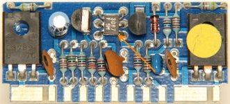
The differential transistors are the 6 or 7 legged devices on the audio driver boards (near the output transistors). The arrow in the attached photo points to the differential transistor. If yours uses the 7-legged transistor, it will be slightly different.
Attachments
The differential transistors are the 6 or 7 legged devices on the audio driver boards (near the output transistors). The arrow in the attached photo points to the differential transistor. If yours uses the 7-legged transistor, it will be slightly different.
Is there a way to check these with the multimeter?
It's unlikely that the differential transistor is causing the output to be low.
Do both gain controls have the same range of rotation?
Are they both set to the maximum level?
Email soundstream. Get the schematic diagram from them and email me a copy.
Burn the following file to a CD (or save it to whatever you're using for a signal source) and drive a strong signal into both channels. Set the crossovers to full range and set the gains to the maximum level. Measure the AC voltage on the center pin of the RCA jack feeding the amp and confirm that you have at least 1/2v AC. When you send me the schematic, I'll tell you what to do next.
http://www.bcae1.com/temp/100hz300seconds.zip
The differential transistors are the 6 or 7 legged devices on the audio driver boards (near the output transistors). The arrow in the attached photo points to the differential transistor. If yours uses the 7-legged transistor, it will be slightly different.
Thanks Perry I got a family thing going on here. I gotta be at the hospital all day tomorrow also.
The diff transistor is a source of that 20 milli-volt DC output you got in that one channel < Most likely > Thx Perry for the pic ....
On the road back home today. Will pick this back up tomorrow. Emailed SS and waiting for the schematics.
Ebay seller is stepping up and asking how I want to resolve. Back story: Bought this off Ebay as fully functional. When it arrived it showed the story I told here.
What is fair as far as renumeration from the seller?
Ebay seller is stepping up and asking how I want to resolve. Back story: Bought this off Ebay as fully functional. When it arrived it showed the story I told here.
What is fair as far as renumeration from the seller?
[QUOTE} renumeration
Remuneration?
remuneration/renumeration[/QUOTE]
Hmm? I guess I thought I was smarter than I am. Just looking for advice on what the diy fix is worth. However that may need to what until I know what exactly is wrong. Thanks for the check!
Thanks for the direction!!!
The FEBs are the little boards that stand up perpendicular to the main board, right? I'm a novice with electronics but have no problem digging into this. However, it is a little daunting to look at the guts and understand where to start probing for problems.
Great! I'll start with cleaning.
What does the diff transistor look like? Do you have these parts (switches, FEB or diff transistors) in stock? Where are you in NorCal? I'm in Nevada City right now. Wondering if your close by???
I am south of Sacramento by a fair piece in the central valley. Pretty much the middle of nowhere. So close may not be the best way to describe my where-abouts. Look at a Cali map and find Monterrey bay, then pull into the central valley with your finger and just over the hills there I be in San Joaquin valley
I might be able to source your parts you need from a old friend of mine. Perry knows who I am talking about. PM me and I will try to make the connection for you.
It's unlikely that the differential transistor is causing the output to be low.
Do both gain controls have the same range of rotation?
Yes
Are they both set to the maximum level?
They are not all the way up as the little 4" MB Quarts, in the back, can't handle it all. And the front I can't turn all the way up as the working channel over gains (?) and starts sounding bad despite being HAT Clarus 6.5 comps. However, when the gain gets to an acceptable level on the working channel the 'dead' channel is inaudible.
Email soundstream. Get the schematic diagram from them and email me a copy.
I've got the diagram but cannot send through the forum email link. I need your address to send it directly. Pm it to me and I'll send the schematic right over. I'll post it here also to see if the resolution is good enough.
Burn the following file to a CD (or save it to whatever you're using for a signal source) and drive a strong signal into both channels. Set the crossovers to full range and set the gains to the maximum level. Measure the AC voltage on the center pin of the RCA jack feeding the amp and confirm that you have at least 1/2v AC. When you send me the schematic, I'll tell you what to do next.
http://www.bcae1.com/temp/100hz300seconds.zip
The output from the RCAs from the HU all measure .506-.509 VAC. Can't figure why setting the gains would matter as I have to pull the input RCA to measure the voltage. I must have misunderstood what you want me to do with the RCA pin.
Attachments
- Status
- This old topic is closed. If you want to reopen this topic, contact a moderator using the "Report Post" button.
- Home
- General Interest
- Car Audio
- Newbie Soundstream ref 604 repair