Ok, today I thought I'd follow the instructions on Perry's website for measuring power output.
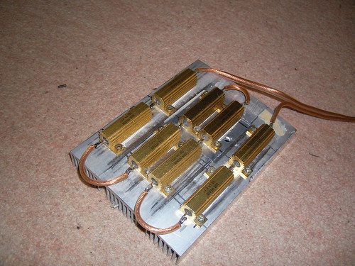
I built my dummy load out of eight 1 ohm 50 watt resistors screwed down to a heatsink that I rescued out of one of those crappy peltier effect refrigerators.
The amp I chose is a no name type monoblock that came from an amplified subwoofer. I gave $2 for it because it was broken. I rewound the toriod due to the primary being shorted and replaced the associated PSU fets.
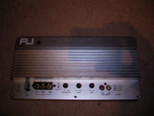
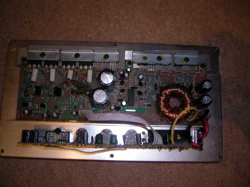
The advertised rating of the amplifier is 500w RMS and 1600w Peak. I'm guessing that this is at 2ohms, because the box it was removed from uses two 4 ohm woofers in parallel. It uses 4 IRFZ44's in the PSU, and a pair of 2SB688 and 2SD718 in parallel in the output stage.
I measured at 8, 4 and 2 ohm loads at 100Hz, because of the integrated crossover.
Results are rounded, but I pretty much got 50w at 8ohms, 75w at 4 ohms and 100w at 2 ohms!
Also, just for fun, I measured the domestic amplifier I use to power the speakers attatched to my computer. Its an old Technics amp, rated at 40wpc.
Measuring at 8 ohms at 1KHz I got 60w, and 4 ohms 80w.
I guess there is a lot to be said about misleading power ratings!
I built my dummy load out of eight 1 ohm 50 watt resistors screwed down to a heatsink that I rescued out of one of those crappy peltier effect refrigerators.
The amp I chose is a no name type monoblock that came from an amplified subwoofer. I gave $2 for it because it was broken. I rewound the toriod due to the primary being shorted and replaced the associated PSU fets.
The advertised rating of the amplifier is 500w RMS and 1600w Peak. I'm guessing that this is at 2ohms, because the box it was removed from uses two 4 ohm woofers in parallel. It uses 4 IRFZ44's in the PSU, and a pair of 2SB688 and 2SD718 in parallel in the output stage.
I measured at 8, 4 and 2 ohm loads at 100Hz, because of the integrated crossover.
Results are rounded, but I pretty much got 50w at 8ohms, 75w at 4 ohms and 100w at 2 ohms!
Also, just for fun, I measured the domestic amplifier I use to power the speakers attatched to my computer. Its an old Technics amp, rated at 40wpc.
Measuring at 8 ohms at 1KHz I got 60w, and 4 ohms 80w.
I guess there is a lot to be said about misleading power ratings!
There is no inductor on the output of the power supply, so i guess we have to assume it's not regulated. The output power will therefore depend on the battery or PSU voltage you fed into it. From what i have seen they tend to test these things with a 14.4V input, no doubt that'd increase the output a tad, but not by more than 400W RMS 
Maybe it might make another 25 - 40W RMS into 2 ohms, though this depends on what the input voltage was that you gave it.
Kind of makes me laugh as years ago i bought a Maplin PCB for an SMPS that was to be used in a car. I'll not go into the real mess that basicly had a regulated supply with NO output inductor, thus causing the switching Mosfets to produce loads of heat I wound a suitable inductor & added an extra couple of turns to the transformer (didn't wind it like they did either as that was pretty ropey) & managed to get a nice clean 60W RMS per channel with 3 channels driven.
I was eventually given the thing back, having sold it to a friend. Still works, he just didn't have a use for it any longer.
Maybe it might make another 25 - 40W RMS into 2 ohms, though this depends on what the input voltage was that you gave it.
Kind of makes me laugh as years ago i bought a Maplin PCB for an SMPS that was to be used in a car. I'll not go into the real mess that basicly had a regulated supply with NO output inductor, thus causing the switching Mosfets to produce loads of heat
I wound a suitable inductor & added an extra couple of turns to the transformer (didn't wind it like they did either as that was pretty ropey) & managed to get a nice clean 60W RMS per channel with 3 channels driven.I was eventually given the thing back, having sold it to a friend. Still works, he just didn't have a use for it any longer.
Just for giggles did you measure the resistance of the load at temperature? Most will change with temperature. You could also measure the current through the load then calculate resistance.
I have done those measurements on all the amps I work on, just for fun really. For example the MA audio, power acoustik all read way below advertised value, a sony amp was spot on to advertised power. The RF amps are above advertised power.
I have done those measurements on all the amps I work on, just for fun really. For example the MA audio, power acoustik all read way below advertised value, a sony amp was spot on to advertised power. The RF amps are above advertised power.
I was using a spare 12v car battery I have. I should get or make decent bench PSU, so I can see what these things can do at 14.4v.
I didn't measure the resistance of the load at temperature, but that's a good idea, should make the results more accurate.
What I really wanted to measure was my Sumo Andromeda domestic amplifier, but after getting it out of storage, it has no output from either channel, despite putting it away in full working order
- Status
- This old topic is closed. If you want to reopen this topic, contact a moderator using the "Report Post" button.