Ive had an interesting history with this amp. I bought it blown hoping to fix it on my own, but I did not have the skill nor time to finish it. So I sent it to DD for repair.
I get it back and within the first day of wiring it down to 1ohm it goes boom . So I check it out and notice a blown PS FET (IRFP 1405). I pulled it and the one next to it and put in replacements, with new gate resistors.
I powered up the amp using a 15 amp fuse to test it out. Once remote voltage is applied I hear a high pitched squeal/whistle with intermittent crackling coming from the PS section. Sounds to be coming from the transformers but it is hard to distinguish. I push on the transformers but there is no chance in sound.
The protection light comes on for the first 5 sec then goes out, but no green light. It doesn't draw enough current to blow the 15 amp fuse, and nothing gets hot. I tested the out puts with a DMM and none indicated a direct short.
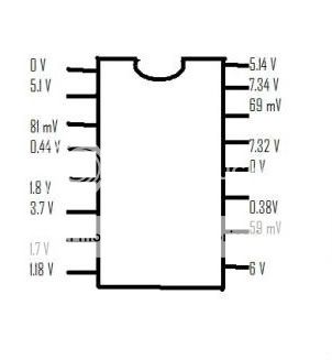
I then tested the IC (SG3525A) with the meter. I have included the results below. Also when I touched the probe to the pin that reads 59 mV the sound comming from the PS section changed (got louder/screetch).
I hope one of you gurus could help me out. Thanks in advance.
I get it back and within the first day of wiring it down to 1ohm it goes boom
. So I check it out and notice a blown PS FET (IRFP 1405). I pulled it and the one next to it and put in replacements, with new gate resistors.I powered up the amp using a 15 amp fuse to test it out. Once remote voltage is applied I hear a high pitched squeal/whistle with intermittent crackling coming from the PS section. Sounds to be coming from the transformers but it is hard to distinguish. I push on the transformers but there is no chance in sound.
The protection light comes on for the first 5 sec then goes out, but no green light. It doesn't draw enough current to blow the 15 amp fuse, and nothing gets hot. I tested the out puts with a DMM and none indicated a direct short.
I then tested the IC (SG3525A) with the meter. I have included the results below. Also when I touched the probe to the pin that reads 59 mV the sound comming from the PS section changed (got louder/screetch).
I hope one of you gurus could help me out. Thanks in advance.
Part of the problem could be the low voltage reaching the IC. It's rated to work from 8-40v. What was the DC voltage on the B+ and remote terminals when you measured the voltages above?
Power was supplied using a 12volt battery. So 12V should have been reaching the amp, I will check again.
The same kind of sounds (buzzing/wizzing) were noted when the amp first blew still connected in my car.
I was also surprised to not see ~12 volts at the IC.
I tested the voltage again, and it was a solid 12V at the B+ and REM leads. But still only ~7.4 V on the pin of the IC. I will study the driver board a little closer to look for any obvious problems.
I also noticed a loud clicking noise after power had been applied for a few seconds. This sound would typically occur when the amp came on (almost like a switch). After the click the amp would go from protect to power (when the amp was working). But now it clicked a few times and still no power.
I believe the parts responsible for this are these little black boxes labeled "Handouk RA-A12S" which are adjacent to where the speaker leads leave from the output section. They are apparently some type of coil encased in a black plastic box. I am not too familiar with amps to know what these are/if they could be the problem. Perhaps some style of solenoid?
I hope I was being clear in my explanation.
wait what? you send it to DD and then it blow again? did you ever call them and talked with them about this?
Yeah Ive been talking with them...and its a big hassle. They outsource their repairs and it was a very questionable repair (wont get into details). It would probably cost me just as much in shipping it back to DD as it would be to repair myself.
So it is kind of a goal of mine to fix this amp myself...I will see how it goes.
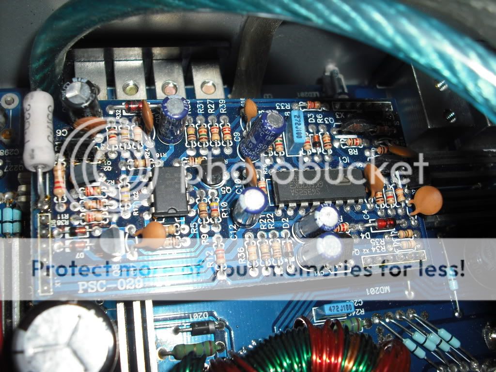
I am having a hard time following the circuit for the PS driver card, it might have to be removed to view it completely (which I don't want to do).
I am going to make some Emails and see if I can come across some schematics for this bad boy.
also go to soundpressure.com, since that is DD forum, you might get some extra help you need. I say go for DIY repair, since as you say, all fets are ok(?), so expensive part is intact, now I would say you need to get yourself scope, or you really don't know what is going on in circuit...it would be much more easy to find the problem, but yes, those 7v on SG is WAY low, fets are open, but not with a lot of voltage margin, so good start is there
also go to soundpressure.com, since that is DD forum, you might get some extra help you need. I say go for DIY repair, since as you say, all fets are ok(?), so expensive part is intact, now I would say you need to get yourself scope, or you really don't know what is going on in circuit...it would be much more easy to find the problem, but yes, those 7v on SG is WAY low, fets are open, but not with a lot of voltage margin, so good start is there
Yeah I have been looking on soundpressure today
. There was 1 obviously blown PS FET when I checked it out. I replaced it along with another questionable one. I will need to go through it again to see if I can find any more blown ones.
I just found it interesting that It would come out of protect, but just make those weird noises.
I am not pressed for time, so I would like to do it right.
Thank you guys for your help
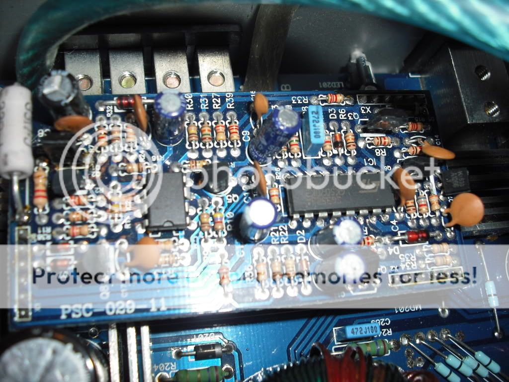
You shouldn't need to trace the circuit to find the transistor that powers the 3525. Remove power from the amp. Set your meter to ohms or diode check. Place one meter probe on the B+ terminal. Touch each leg of each of the transistors on the driver board. Do any read ~0 ohms?
With one probe on pin 13 of the 3525, do you read anything near 0 ohms to any leg of any transistor on the driver board?
With one probe on pin 15 of the 3525, do you read anything near 0 ohms to any leg of any transistor on the driver board?
Does any individual transistor have direct connections to both the B+ terminal and either pin 13 or 15 of the 3525?
You shouldn't need to trace the circuit to find the transistor that powers the 3525. Remove power from the amp. Set your meter to ohms or diode check. Place one meter probe on the B+ terminal. Touch each leg of each of the transistors on the driver board. Do any read ~0 ohms?
With one probe on pin 13 of the 3525, do you read anything near 0 ohms to any leg of any transistor on the driver board?
With one probe on pin 15 of the 3525, do you read anything near 0 ohms to any leg of any transistor on the driver board?
Does any individual transistor have direct connections to both the B+ terminal and either pin 13 or 15 of the 3525?
well that is certainly a much better way of tracing the circuit haha. Wow I am surprised I didn't just think of that on my own, you can tell I have little experience in regards to circuits.
After checking over the card I found 2 transistors with low resistance B+ connections, however none of the legs led to either of the 2 pins on the IC with little resistance.
Could blown PS FETs be responsible for the weird readings on the IC? I will be checking over them again, and will remove the questionable ones. Is there an easy way to remove them without snipping the legs, Id assume a solder sucker/solder braid would do the trick?
Blown PS FETs would only likely lead to low voltage if they were dragging the 12v power supply voltage down.
See if you can trace the circuit from pins 13 and 15 of the 3525 to either of those transistors. If the voltage passes through a diode or a resistor, that could explain why you're not seeing a direct connection. A lighted magnifying glass will make this easier. Of course, there are traces on the bottom of the driver board so visually following traces may not be possible.
Don't try removing the driver board.
Which components were you going to remove (but didn't want to cut the legs)?
Blown PS FETs would only likely lead to low voltage if they were dragging the 12v power supply voltage down.
See if you can trace the circuit from pins 13 and 15 of the 3525 to either of those transistors. If the voltage passes through a diode or a resistor, that could explain why you're not seeing a direct connection. A lighted magnifying glass will make this easier. Of course, there are traces on the bottom of the driver board so visually following traces may not be possible.
Don't try removing the driver board.
Which components were you going to remove (but didn't want to cut the legs)?
I was referring to removing the PS FETs to test them out of the circuit. I removed the blown ones by snipping the legs, but would like to avoid that on FETs that could be good.
Yeah it seems as if the majority of the traces are on the bottom of the card. But I will continue to check them out
Apply additional solder to all 3 legs and lay the tip of the soldering iron across all 3 solder connections to heat them all at once. The transistor should essentially fall out of the board when the solder becomes molten on all 3 legs. If there's excessive solder on top of the board (component side of the board), you may have to remove it beforehand to make it easier to get the solder hot enough.
- Status
- This old topic is closed. If you want to reopen this topic, contact a moderator using the "Report Post" button.
- Home
- General Interest
- Car Audio
- DD Z1 amp issues