hi all,
i have a huge MTX TA92001 with some problems in the power supply.
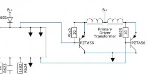
The oscillator is TL494 (smd) in open collector mode (with pull-up resistor), that drives a pair of darligton MJD127 (smd) with collector to GND, base to tl494 pin 8 (or 12), and emitter to a tiny transformer. from base, to collector there is a 10ohm resistor.
This tiny trafo has 1 primary (it seems push pull with CT to 12v) and 2 secondaries. The primary has the 2 pulses from tl494 open collector, and generates in the secondary, 2 pulses out of phase, for driving gates of mosfet (STW80NF06).
Gate resistor is 10 ohm.
This is not a push pull smps, because mosfet drain are at 12V, and source is floating and goes to toroid. Center tap of toroid primary is at GND. Only one secondary.
What kind of smps is it? half bridge?
next problem.
I tried to fix one part/toroid of smps (i fix thousand of car amps in italy), but:
1- smps stars without remote on
2- idle current is 1,5A, generates +-100V @12Vin, output stage is OK (no shorts). no hot component. output voltage very clean, low ripple.
3- with remote on, the current rise to 1,7A (i think comparators turn on)
then, i tried to elevate Vin to 14,5V, and i saw that +-100V rise (oh..unregulated).
but when i rise 14V, i heard....boooom!
A small route near comparators (lm339) smokes, and broken.
I resoldered it, and i re-turn on the amplifier....but nothing!
TL494 is standby, heat up, its outputs are HIGH. its inputs are set wrong, with +IN at 0v, and -IN at 5V.....obviously doesn't work. tl494 is ok because i put a new one with same results.
i'm going crazy because the pcb is multilayer and some routes appear and disappear
i wanna rebuilt oscillator, with sg3525 (that i know very well, and i use it for several smps projects) in aftermarket board, by me.
i tried to use my "test board" (fully working) based on sg3525+Ir4427, fully unregulated (but there is an option for feedback, with zener+opto).
i removed, for safety, the diode AKA e KAK from original power supply, tl494 and darlington MJD127 to isolate original circuit from new board .
i linked IR4427 outputs, first time to primary of tiny transformer, then directly to the gate of mosfets.
the power supply starts but works bad. Idle current is 1,5A (but now, there's no output mosfet!!).
Gate waveforms are optimal, no ringing, but IR4427 heat up.
Drain stays at 12V (ok)
Sources turn on very bad. With 100kHz, the waveforms is likely a distorted sinewave 6Vpp (mmm..12 : 2 = ??) but no DC voltage.
I reduced oscillator frequency to 30kHz, and is become more square wave, but again 6Vpp.
Test mosfets (working irfz44..they're cheap) heat very much!
A note:
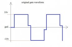
when the power supply started first time, and generates +-100V correctly, gate waveforms are: positive side @10V, gnd (deadtime?), negative side @-10V, AC and DC coupled o-scope. Frequency is about 25kHz..very low.
How could i generate that waveforms with sg3525? i need tiny trafo and open collector mode?
sorry for the long description.
i'm sorry but i can't make photos of first start waveforms (when it works and generates +-100V)..because now, same setting, doesn't work
Thank you everyone!
i have a huge MTX TA92001 with some problems in the power supply.
The oscillator is TL494 (smd) in open collector mode (with pull-up resistor), that drives a pair of darligton MJD127 (smd) with collector to GND, base to tl494 pin 8 (or 12), and emitter to a tiny transformer. from base, to collector there is a 10ohm resistor.
This tiny trafo has 1 primary (it seems push pull with CT to 12v) and 2 secondaries. The primary has the 2 pulses from tl494 open collector, and generates in the secondary, 2 pulses out of phase, for driving gates of mosfet (STW80NF06).
Gate resistor is 10 ohm.
This is not a push pull smps, because mosfet drain are at 12V, and source is floating and goes to toroid. Center tap of toroid primary is at GND. Only one secondary.
What kind of smps is it? half bridge?
next problem.
I tried to fix one part/toroid of smps (i fix thousand of car amps in italy), but:
1- smps stars without remote on
2- idle current is 1,5A, generates +-100V @12Vin, output stage is OK (no shorts). no hot component. output voltage very clean, low ripple.
3- with remote on, the current rise to 1,7A (i think comparators turn on)
then, i tried to elevate Vin to 14,5V, and i saw that +-100V rise (oh..unregulated
).but when i rise 14V, i heard....boooom!
A small route near comparators (lm339) smokes, and broken.
I resoldered it, and i re-turn on the amplifier....but nothing!
TL494 is standby, heat up, its outputs are HIGH. its inputs are set wrong, with +IN at 0v, and -IN at 5V.....obviously doesn't work. tl494 is ok because i put a new one with same results.
i'm going crazy because the pcb is multilayer
and some routes appear and disappeari wanna rebuilt oscillator, with sg3525 (that i know very well, and i use it for several smps projects) in aftermarket board, by me.
i tried to use my "test board" (fully working) based on sg3525+Ir4427, fully unregulated (but there is an option for feedback, with zener+opto).
i removed, for safety, the diode AKA e KAK from original power supply, tl494 and darlington MJD127 to isolate original circuit from new board .
i linked IR4427 outputs, first time to primary of tiny transformer, then directly to the gate of mosfets.
the power supply starts but works bad. Idle current is 1,5A (but now, there's no output mosfet!!).
Gate waveforms are optimal, no ringing, but IR4427 heat up.
Drain stays at 12V (ok)
Sources turn on very bad. With 100kHz, the waveforms is likely a distorted sinewave 6Vpp (mmm..12 : 2 = ??) but no DC voltage.
I reduced oscillator frequency to 30kHz, and is become more square wave, but again 6Vpp.
Test mosfets (working irfz44..they're cheap) heat very much!
A note:
when the power supply started first time, and generates +-100V correctly, gate waveforms are: positive side @10V, gnd (deadtime?), negative side @-10V, AC and DC coupled o-scope. Frequency is about 25kHz..very low.
How could i generate that waveforms with sg3525? i need tiny trafo and open collector mode?
sorry for the long description.
i'm sorry but i can't make photos of first start waveforms (when it works and generates +-100V)..because now, same setting, doesn't work
Thank you everyone!
Last edited:
thanks Perry for the reply,
MTX say "semi-unregulated"....mmm
no transistor are failed.
Original STW80NF06 were removed because they're expensive if failed, and i use irfz44 unclamped, one per primary.
at idle, they shoudn't heat if there's a square wave...but it isn't.
they heat because they don't fully turn on i think, and heat up IR4427..normally cold in other designs.
the main problem is driving gate well, i think.
normal waveform, 0-12V given by IR4427 work on classical push-pull (with CT @12V)..but here not.
i paint an example of original gate waveform (other gate is out of phase), when amp turn on and generates +-100V.
is it right?
why negative side??? n-channel mosfet are OFF both Vds=0 or Vds<0
Attachments
photos with sg3525+ir4427:
gate (ringing because there are cable in air from my board, to mtx):
http://img693.imageshack.us/img693/9950/dscn0909n.jpg
source:
http://img707.imageshack.us/img707/1791/dscn0907u.jpg
current:
http://img682.imageshack.us/img682/8253/dscn0908d.jpg
timebase is 10us/div, and voltage is 5V/div.
strange source signal, or not?
thanks
The following file shows the typical waveforms for this type of power supply. It's a large file so you should expect it to take a while to download.
http://bcae1.com/temp/mtxamp01.swf
The driver transformer produces both positive and negative voltage swing. The sources of the power supply FETs follow that waveform.
In this amp, it's better to have all power transistors clamped to the heatsink. The voltage regulators, in particular, can fail within seconds and do extensive damage when they fail.
oh yes! perfect!
the center tap of that driver transformer is @12V?
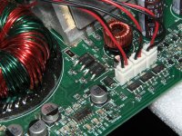
this is the route that smokes the first time.
http://img203.imageshack.us/img203/377/dscn0912.jpg
Regulators are clamped, Diodes removed.
STW80NF06 original.
perfect!the center tap of that driver transformer is @12V?
this is the route that smokes the first time.
http://img203.imageshack.us/img203/377/dscn0912.jpg
Regulators are clamped, Diodes removed.
STW80NF06 original.
In the smaller/older amps, the remote was driven into one of the inputs of an LM339 (via a resistor). This amp is likely similar.
This amp also has the ability to turn on when DC is driven into the RCA inputs. The components in the small group on the corner of the board (including Q211) are part of that circuit. The collector of Q211 likely drives a PNP transistor near the LM339s.
I'll be away from my computer for a while so it may be a while before I can answer any other questions that you may have.
One more thing... The 494 will likely always be in operation (clock pulses on pin 5). If that's what you referred to, that's normal. If the amp's power supply doesn't shut down (continues to drive the power supply FETs) when you remove the remote voltage, that's not normal.
- Status
- This old topic is closed. If you want to reopen this topic, contact a moderator using the "Report Post" button.
- Home
- General Interest
- Car Audio
- MTX TA92001 power supply questions & fix