I have a BAMF1600/4 series that I would like a schematic for. I sent off an email to Power Acoustik and haven't heard anything.
I am more interested in the output config, it uses all irf540's. Not what I am used to seeing. So any schematic with that config would be useful.
Thanks,
cory
I am more interested in the output config, it uses all irf540's. Not what I am used to seeing. So any schematic with that config would be useful.
Thanks,
cory
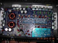
Here is a pic of the board. It has bias test points for all 4 channels, what am I looking for on those. Right now they all read differently. When I adjust the bias pot for channel one, it will pop a 10 amp fuse when adjusting in either direction. With Rockford amps I just put a voltmeter across my .005ohm series resistor in my supply line and watch for the mV's to shoot up, then adjust back a little. I don't see that spike with this amp.
When I load channel 1 with 3 ohms I lose the lower half of the sine wave. Unloaded I can get ~22Vrms out, normal channel is 24.5Vrms.
cory
When I load channel 1 with 3 ohms I lose the lower half of the sine wave. Unloaded I can get ~22Vrms out, normal channel is 24.5Vrms.
cory
Attachments
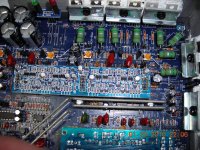
The source resistors appear to be intact but if one is well out of tolerance, that could cause the amp to clip early.
Is the defective channel the only one that causes an increase in idle current when the bias pot is turned clockwise or counter-clockwise?
Adjusting the bias by monitoring the idle current worked on the 2200/2 I repaired.
The bias is important on this amp because (if I'm not mistaken), the bias pot controls the current through the differential amplifier and if there is insufficient current through the differential amp, the following stages can't be driven properly.
In addition to checking all of the driver transistors, check the SMD resistors for that channel on the driver board.
- Status
- This old topic is closed. If you want to reopen this topic, contact a moderator using the "Report Post" button.
- Home
- General Interest
- Car Audio
- Power acoustik schematic