Did you pull the rectifiers away from the sink to see if any had broken legs? They sometimes break inside the body of the rectifier so you have to push tnel to the side to make sure they're not broken.
The reason I ask is that there's definitely output from the transformer but there's no DC. You should read ~+50v DC on the center legs of the 600 series rectifiers and ~-50v on the outer legs of the 700 series rectifiers. I have one here and powered it up to confirm that that's what you should read.
The reason I ask is that there's definitely output from the transformer but there's no DC. You should read ~+50v DC on the center legs of the 600 series rectifiers and ~-50v on the outer legs of the 700 series rectifiers. I have one here and powered it up to confirm that that's what you should read.
Did you pull the rectifiers away from the sink to see if any had broken legs? They sometimes break inside the body of the rectifier so you have to push tnel to the side to make sure they're not broken.
The reason I ask is that there's definitely output from the transformer but there's no DC. You should read ~+50v DC on the center legs of the 600 series rectifiers and ~-50v on the outer legs of the 700 series rectifiers. I have one here and powered it up to confirm that that's what you should read.
Yea, I did. They feel pretty solid
Not sure how the rectifier series system works, but they are mur3040pt if that helps.
Do you read ~0 ohms between the RCA shields and the secondary center taps of the power transformers?
If you do, I think you need to pull them and check them thoroughly. It's unlikely that they're open if the legs aren't broken but there seems to be an open/broken connection somewhere.
If you do, I think you need to pull them and check them thoroughly. It's unlikely that they're open if the legs aren't broken but there seems to be an open/broken connection somewhere.
Yes. Make sure they read ~0.4v (on diode check) with the black probe on the center leg and the red on the outer legs. With the probes reversed, they should read OL (or whatever your meter reads with open leads). Do this for all four.
While you have it out of the sink, look for open/burned traces.
While you have it out of the sink, look for open/burned traces.
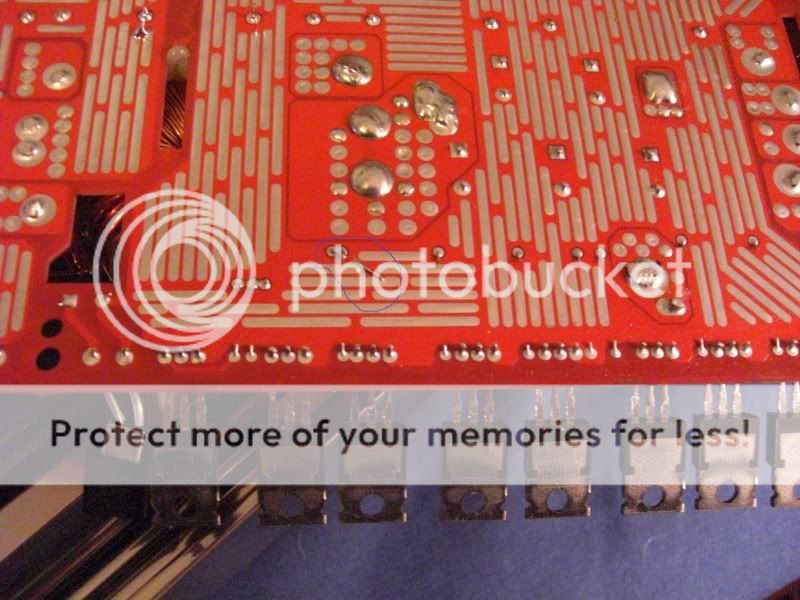
Well what i noticed almost looks like an unused piece of solder which is bridging two traces together. I also compared the board to the pics that you have in your tutorial and I'm pretty sure it is not in your pics.
Not sure exactly where you are talking about, but I haven't noticed anything significant.
Not sure exactly where you are talking about, but I haven't noticed anything significant.
That immediate area except for the two resistor leads is the same piece of copper. Is the wire touching the two resistor solder connections?
If it's not touching the resistor solder connections, it's not a problem.
When you tested the diodes, did you find ~0.4v (on diode check) across each diode of the rectifier and when you reversed the probes, did it read OL?
If it's not touching the resistor solder connections, it's not a problem.
When you tested the diodes, did you find ~0.4v (on diode check) across each diode of the rectifier and when you reversed the probes, did it read OL?
- Status
- This old topic is closed. If you want to reopen this topic, contact a moderator using the "Report Post" button.
- Home
- General Interest
- Car Audio
- Repair Help on Orion 2500d