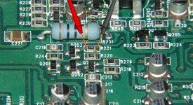
With the amp powered up and the black probe on chassis ground, post the DC voltages on Q219, 220 and 224. For the SMD transistor, the pins are 1 and 2 on the bottom (left to right) with 3 on top.
Q220
Leg 1:
Leg 2:
Leg 3:
Q219
Leg 1:
Leg 2:
Leg 3:
Q224
Leg 1:
Leg 2:
Leg 3:
Q220
Leg 1:
Leg 2:
Leg 3:
Q219
Leg 1:
Leg 2:
Leg 3:
Q224
Leg 1:
Leg 2:
Leg 3:
With 212 out of the circuit, what is the DC voltage on it's solder pads (square solder pad = pin 1)?
Q212 pads
Pin 1:
Pin 2:
Pin 3:
What is the voltage on the terminals of Q202 and Q203 (see attached for layout)?
Q202
Pin 1:
Pin 2:
Pin 3:
Q203
Pin 1:
Pin 2:
Pin 3:
Q212 pads
Pin 1:
Pin 2:
Pin 3:
What is the voltage on the terminals of Q202 and Q203 (see attached for layout)?
Q202
Pin 1:
Pin 2:
Pin 3:
Q203
Pin 1:
Pin 2:
Pin 3:
Attachments

- Status
- This old topic is closed. If you want to reopen this topic, contact a moderator using the "Report Post" button.
- Home
- General Interest
- Car Audio
- Rockford Fosgate 100x2