In amps that use driver transistors instead of the driver ICs, it's common for a single output to fail without doing further damage but I don't remember if that's the case with the amps that use the driver ICs (I haven't worked on many of them in the last 10 years).
Evening Perry, Sorry to barge in, but I just repaired a similar Alpine recently and still remember the others I did over the years and usually you are very correct and the driver IC survives, but in this case with melted fuse holders and bad caps, incorrect outputs and shorted dead on, etc... I am thinking the $3.00 to $12.00 US will not pull the budget down too much plus when you get the combined circumstance the gentleman has described the odds are not in the favor of the owner too much.
The UPC1270H device has a limited market and can be a little tough to find but there is a source on e-pay for about $12.00 US, I bought the $4.00 ones a while back myself before I found my spares I had stashed. They are getting tough to come by as they are very old < 18 years at least >.
Anyway just chiming in with all the recent info and experience I had running down the driver IC just a month ago. Please keep up the fine support and work your doing, it's nice to see quality....
")
Hello,
Thanks for the insight everyone.
As far as the driver IC, since audiolab stocked them, I will just get a piece just in case. The one in the amp looks like original, never been replaced. But I think all of the power supply transistor has been replaced (8 of them, current part is 2sd1065).
Im still trying to source the power supply caps locally so that I can test run it. Would the old ones be ok to test run it? Its not shorting, holding charge, but one of them loosing much faster than the other while measuring in with DVM, after charging it with small DC (6v).
I would like to see if there are more things to purchase, since i pay expensive shipping ;(
Thanks and regards,
Ben
Hello,
Test run the amp. Its working. Measured from center of output transistor to non bridging terminal, 58.2v. I didnt start the car, DC input was around 12.5V to amp. DC offset while no input connected is 0.12v, a bit high, is this normal?
Played music as well, sounds fine on all channel except the one without the output transistor.
Would 35v rated caps be ok? Seems really close to 70v if its not regulated.
When I do replace the output transistor, can I still bridge the channel safely?
Thanks much for the help,
Ben
Test run the amp. Its working
. Measured from center of output transistor to non bridging terminal, 58.2v. I didnt start the car, DC input was around 12.5V to amp. DC offset while no input connected is 0.12v, a bit high, is this normal? Played music as well, sounds fine on all channel except the one without the output transistor.
Would 35v rated caps be ok? Seems really close to 70v if its not regulated.
When I do replace the output transistor, can I still bridge the channel safely?
Thanks much for the help,
Ben
If I remember correctly, Alpine 3554 uses C-L-C filter after diode rectifier. If so, the first C (the one after diode rectifier, before L) should be higher than 35V rating, like 50V or 68V. All the C's (before and after L) should be replaced, due to age, leaking or drying.
The ones after L can be 35V if you measure rail to rail voltage about 58V2.
The ones after L can be 35V if you measure rail to rail voltage about 58V2.
Hello,
After the dual rectifier, it has a 470uf 35v caps, before the small inductor and the big caps. The big caps are the only ones that have 40v rating. Would it be alright to assume since after the duals the caps rating are 35v, its alright to have the big caps 35v as well? Rail is 58.2v thats correct.
Thanks and regards,
Ben
PS: Pak Lumanauw, apakah di glodok lengkap utk komponen, apa kita harus pesan keluar terus utk spare parts yg khusus/'boutique'? Saya tau kalo komponen 'biasa' di toko2 elektronik kecil ada. Salam.
Hi, Ben,
Like Perry ask, is it 58V2 from rail to rail or from 0V to one rail voltage?
Usually in C-L-C filter, the first C has the biggest ripple, usually this one leaks first. I still think it's better to put capacitor with rating >35V in that position. And can safely use 35V rating capacitor for the last C (if the voltage is 58V2 between rail to rail = 28V6 between ground and one rail). You can compare the ripple in the first C and the last C using oscilloscope.
Di Glodok ada beberapa toko komponen audio, seperti Leisure Sound (Ayung).
Hello,
Yes, such a silly mistake ;(. I will measure again tomorrow. I already dismantled everything.
Non bridging terminal means 0v line. Am I correct? I Measure to center legs of output terminal, but in AC setting instead of DC.
I think I can replace the caps near the rectifier with higher rating, its a small 470uf caps, the problem areas is the bigger caps, 35v rating will have more choices.
Thanks for the help,
Ben
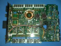
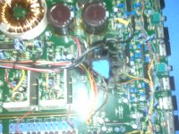
My other amps just died ;( its an alpine 3555. Didnt know how it happened, but it just stop working. When I opened it up. Saw a hole in the pcb, picture attached.
Can this be fixed, or there is no sense to fix this? Looks like one or two caps exploded leaving behind a big hole. Can an exploded caps do this?
Good news is, I can swap the output devices to my 3554. The amps part seems to be working well, no shorted output devices. Its the small signal part that is non functional.
What is that area of the exploded caps? are the 2 transistor, 1 is green and the other is black, part of power supply/regulator of the op-amps?
Kind regards,
Ben
The 3555 can likely be repaired but you may need good quality photos or a schematic diagram to repair the circuit paths that ran through the burned area. Instead of trying to reconstruct the zener regulator that was likely there, you should use a couple of 3 terminal regulators. If the rail voltage isn't more than ±35, you can use the L7815/7915.
The damage was likely caused by the high operating temperature of the regulator transistors. The heat causes the board to become conductive. After the board begins to conduct, the heating increases until the board breaks/crumbles away or the voltage is removed. The caps (if they were leaking electrolyte) can contribute but didn't cause it alone.
If you transfer outputs from one to the other, you only need to do so for one channel.
The missing hole on the last amp picture is where the 16 volt rail regulators were supposed to be located WOW !!!.....Alpine used simple pass element and zener diodes and caps with a current limit resistor for the lower supply. I am guessing a three terminal regulator could be used to replace each rail but my big question is where you gonna hang the TO-220 regulators IC's
I have had to rebuild this section before hence my intimate knowledge of the hole I see. The board likes to burn up as the caps go bad in these amps with age and the lower regs just super heat and cook the board. But I have never seen one as bad as yours.. Dang man some one cut out the PCB....it must have been cooked to carbon to justify such a act.... WOW !!!!
I have had to rebuild this section before hence my intimate knowledge of the hole I see. The board likes to burn up as the caps go bad in these amps with age and the lower regs just super heat and cook the board. But I have never seen one as bad as yours.. Dang man some one cut out the PCB....it must have been cooked to carbon to justify such a act.... WOW !!!!
There should be sufficient clearance under the board. Lay the 3 terminal regs on the heatsink (with insulators) and clamp the board down on top of it. If the board doesn't hold them tightly to the heatsink, use a piece of open cell silicone foam rubber to fill the gap and apply pressure to the regs.
If there isn't sufficient clearance for the body of the reg under the board, position the bodies of the regs in the open part of the board. Drill and tap a hole in the sink and make a clamp to hold the regs down tightly to the sink.
If there isn't sufficient clearance for the body of the reg under the board, position the bodies of the regs in the open part of the board. Drill and tap a hole in the sink and make a clamp to hold the regs down tightly to the sink.
- Status
- This old topic is closed. If you want to reopen this topic, contact a moderator using the "Report Post" button.
- Home
- General Interest
- Car Audio
- Fixing Alpine-3554