I could use some help! Please bear with my lenghty post:
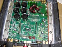
I'm working on this broken amp I bought through ebay a few years ago. Its got some battle scars but is working again to some extent. The power supply fets needed replacing as did their drive transistors and resistors. Some traces were burned off the board, etc. I also replaced failed fets in the outputs (using all the same date codes where paralleled) and some of the 0.1 ohm resistors that were missing.
At this point both channels are outputting clean waveforms at low power levels. The channel labeled as "Right" on the rear cover, will output about 23vrms into a 3 ohm resistive load before clipping. The left will only output about 13vrms when clipping occurs.
The main board schematic I have for this 200DSM and a 200ix shows what looks like current sensing protection circuitry. On a hunch that it might have a problem with one of the 0.1 ohm resistors I tried driving a 6ohm load but the clipping still occurred at about the same output voltage. I don't have schematics for any of the module boards.
I've replaced the driver board with a new one I bought a while back from dealsbyjason but this didn't have much of an effect on the point at which clipping occurs.
The power supply rails measure +37.2v and -37.1v. The opamp supplies measure +12.02v and -12.19v.
I attempted to measure (with an oscilloscope) the signals at "pin" 1 of the left and right driver modules with the gain pots adjusted to output the same 2v on each channel. On the right channel (the one that doesn't clip prematurely) I saw virtually no amplitude. On the left channel (the one that clips) I see a couple volts p-p. So am I referencing the wrong point with my scope ground for the left channel or is this telling me that the left channel's output circuitry has very little voltage gain relative to the working channel?
One confusing thing for me is that the schematic shows the left channel's components which use identifiers like "R108". The rear panel is screened "Left" channel by the side of the amp that has component identifiers of "R208", etc.
The clipping I see is very symetrical top and bottom. I'm using a test CD (in a CD player) to drive the inputs. I can swap the L and R inputs with no change in the clipping.
I can adjust the bias pots to eliminate what looks like crossover distortion, and when I turn them up to this point the amp's idle current
(measured at the power input) is about 400mA.
Here is a pic of the amp and schematic: Thanks in advance for your ideas!
Attachments
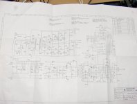
If you look at the schematic, you should see that the inputs to the driver boards are pins 1 and 2. On one channel you should have signal on pin 1 and on the other channel you should have signal on pin 2. If you have signal on the alternate input pin, you likely have defective 10uF capacitors. The caps should shunt 100% of the signal to ground. If you see signal on the alternate input pin, they're not doing their job.
I don't know if this will solve your problem but it is a problem that needs to be resolved before you do any more troubleshooting.
In these old amps, you need to replace all of those 10uf SMD electrolytics. They can cause all sorts of problems.
I don't know if this will solve your problem but it is a problem that needs to be resolved before you do any more troubleshooting.
In these old amps, you need to replace all of those 10uf SMD electrolytics. They can cause all sorts of problems.
Perry,
You were spot-on about the 10uF caps. The trouble seemed to be mostly C203's fault but C202 contributed also. C203 was quite leaky. My ohmeter settled in around 300Kohms across the cap when removed from the board.
I only had some 10uF X7R ceramics laying around so that's what I've got in there now. I thought I read a post a while ago that discussed replacements for this cap but I gave up trying to find it. I did find through a Google search that the factory cap was a Nichicon WC series. I see from that datasheet that it isn't an audio grade but just a general purpose polarized part.
Do you recommend using an aluminum electrolytic?
Bill
Digi-Key - PCE3101CT-ND (Manufacturer - EEV-FC1C100R)
These are the caps I've been using. ^
It was designed for electrolytics. That's what I'd recommend you use as replacements. It's unlikely that you'll find any film caps of equal value that will fit on the pads.
If you decide to replace all of these, I'd recommend that you heat the board from the bottom (I use a 12v lamp, a heat gun will also work) and then apply heat (with your soldering iron) from the top. if the heat from the bottom is sufficient, you can touch your iron to the top of the capacitor and the solder on the pads will melt. This makes it go much more quickly than trying to desolder each one with the iron alone and helps prevent lifting the pads.
- Status
- This old topic is closed. If you want to reopen this topic, contact a moderator using the "Report Post" button.