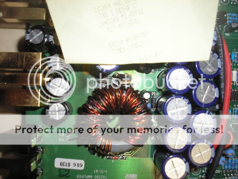
I have an MTX Thunder 2300 here that I would like to bring back to life.It has a bad/shorted channel,blown ps fets,broken rca inputs,missing rectifier,and several other miscellaneous burned/missing components.I read another thread on here about an mtx thunder 2300 and it was very informative however it didn't tell me everything I need to know to try and tackle this repair.In the following picture there is two small square capacitors(i think) next to the transformer that are melted.I need to find the value of these parts:
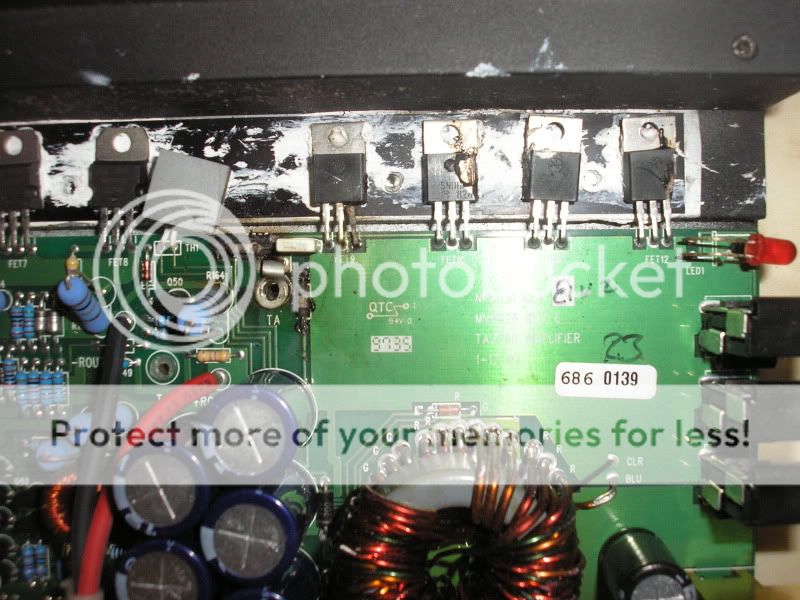
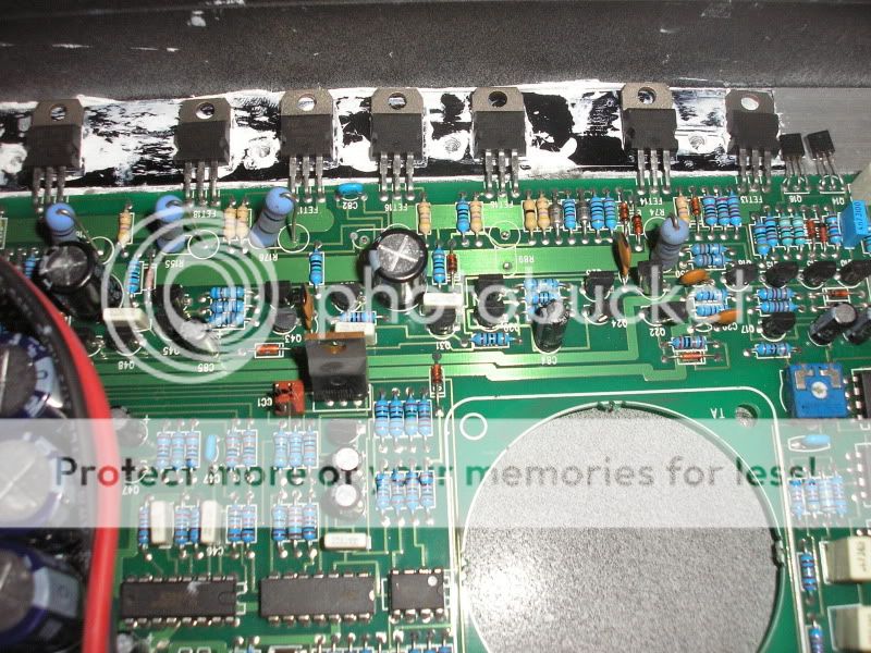
I would also like to double check the value of the burned resistors to the left of the ps fets in this pic:
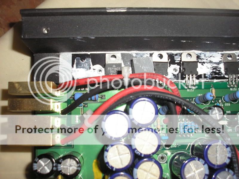
and the part number for the missing rectifier here:
any other info anyone could provide me with would be greatly appreciated.This amp is one of my all time favorites.I want her to be reliable should I be able to bring her back from the dead.I hear these amps are tricky to repair but I believe I am up to the task.
I would also like to double check the value of the burned resistors to the left of the ps fets in this pic:
and the part number for the missing rectifier here:
any other info anyone could provide me with would be greatly appreciated.This amp is one of my all time favorites.I want her to be reliable should I be able to bring her back from the dead.I hear these amps are tricky to repair but I believe I am up to the task.
The burned resistors are 22 ohms.
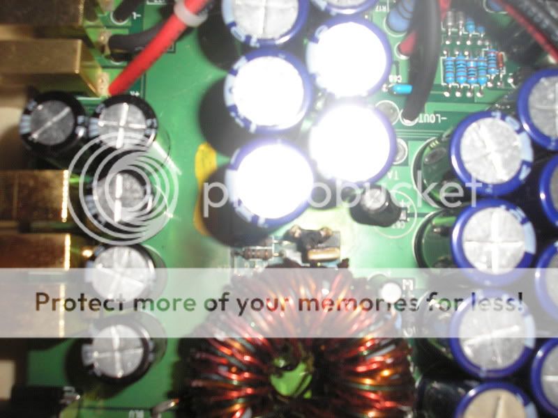
I don't know the value of the caps but one appears to be in reasonably good condition. If you're careful when removing it, you may be able to read the numbers.
The original rectifier was likely an FEN16CT. An MUR1620CTR would be a good sub. Mouser #:
863-MUR1620CTRG
Have you checked the outputs to see if any are shorted?
yes the outputs in one channel are shorted.the other channel appears to be ok.The channel with the shorted outputs had some of the source resistors break/fall out of the board. I've heard that irf3205's are good subs in PS for these amps.Will they work with the 22 ohm resistors that need to be replaced?Is it possible to use say an RFP70N06 instead or would the amp become unstable.
I'd prefer to see the 3205s in this amp. There are only 4 power supply FETs. They need to be as rugged as possible. They should work with the 22 ohm resistors with no problems. Also check the two MPSA56s that drive the driver transformer (Q52/Q53?). The 10 ohm resistors connected between the base and emitter of those transistors rarely fail but you should confirm that they're OK.
If the outputs failed, expect at least a few of the smaller driver/protection transistors to have failed. Begin checking for shorted/leaking transistors. If that doesn't lead you to all of the defective ones, you will either have to compare the readings on one side to the readings on the other side or start pulling them to check them.
If the outputs failed, expect at least a few of the smaller driver/protection transistors to have failed. Begin checking for shorted/leaking transistors. If that doesn't lead you to all of the defective ones, you will either have to compare the readings on one side to the readings on the other side or start pulling them to check them.
I may just replace all of those smaller transistors in the bad channel because they are cheap and I want to make sure it will be a winner.I'll get those 3205's as well.How come there is only two source resistors for the power supply fets?isn't there usually one per fet? maybe I am missing something or have just been out of the game for too long.Really surprised to see only four ps fets for an amp of this size.
those little square capacitors read 123J100 on the top of them. I put the number into mouser's search and it came up with all these: http://www.mouser.com/Search/Refine.aspx?Keyword=123j100
which one of these am I looking for or is it any of these at all? I'm guessing the 100 volt versions would be fine.
which one of these am I looking for or is it any of these at all? I'm guessing the 100 volt versions would be fine.
I finally got everything in I thought I'd need and soldered it in. I replaced all the outputs,small transistors, and source resistors in the bad channel as well as replacing both rectifiers, the ps fets,gate resistors in the ps, and the power supply driver transistors. I powered the amp up and it starts up fine and the newly repaired channel seems to be working well. The amp is not drawing excessive current or doing anything else out of the ordinary. Rail voltage is good as well. The channel that i did not work on however is distorting terribly and the output is considerably lower than the new channel. When i run a sine wave through the amp its plain to see that the severely distorted channel is completely missing the bottom half of the waveform. When I initially checked this amp out i found no shorted outputs in this channel and the current draw is good so i think the outputs are ok. I am thinking the problem lies either in the op amps or driver transistors but i am really just scratching my head as to where to start.
Does the bias control work properly on the other channel?
If so, you may have a defective transistor (or, more likely, multiple defective transistors) in the drive and/or protection circuit. You may have to check every transistor in the channel. You can't simply check for shorted transistors. Many times, the transistors open so you have to confirm that every bipolar driver transistor has two intact junctions.
If so, you may have a defective transistor (or, more likely, multiple defective transistors) in the drive and/or protection circuit. You may have to check every transistor in the channel. You can't simply check for shorted transistors. Many times, the transistors open so you have to confirm that every bipolar driver transistor has two intact junctions.
I replaced every small transistor in the distorted channel. I checked all of the ones I replaced and didn't find any to be defective but at that point having them all removed and having extras on hand I put in all new ones anyway. I either missed one or there was some bad solder contacts because the amp now has clean output on both channels however the previously distorted channel still has less output than the one I replaced the outputs in. It seems as if one of the opamps may be putting out slightly less signal than the other but I will have to look deeper into that later. If you happen to read this , is there a schematic for this amp in your tutorial Perry?
Last edited:
Are both gain controls set the same (maximum) position?
If so, the pots may not be properly aligned. Sometimes the shaft gets pulled out slightly and one gets turned before the shaft is pushed back into place. Make sure that both have the same range of rotation. If they're not properly aligned, the range of rotation for one will be less than the other.
If so, the pots may not be properly aligned. Sometimes the shaft gets pulled out slightly and one gets turned before the shaft is pushed back into place. Make sure that both have the same range of rotation. If they're not properly aligned, the range of rotation for one will be less than the other.
- Status
- This old topic is closed. If you want to reopen this topic, contact a moderator using the "Report Post" button.
- Home
- General Interest
- Car Audio
- MTX Thunder 2300