Holy crap, the 3205's are 110 amps! Yeah, I should definately go for those and pull the z44's. I'll swap the resistors as well. Guess I'll wait a little longer to grease everything and bolt it back together. Wow, I can't believe they squeeze that kind of current capability into a to220 case, definately need to keep those amps cool eh? So even though the originals were rfp50n06 rated at 50 amps and the z44's are pretty close that's not good enough? Will the 3205's make the power supply more reliable, even with the same to220 case?
Last edited:
If you that that's impressive:
http://www.fairchildsemi.com/ds/FD/FDP8440.pdf
The problem with FETs like the one above is that they're so hard to drive.
Are you sure that the 50N06s were original?
The 3205s should make the power supply more reliable. If you use the 3205s, you definitely need to use the 22 ohm resistors.
http://www.fairchildsemi.com/ds/FD/FDP8440.pdf
The problem with FETs like the one above is that they're so hard to drive.
Are you sure that the 50N06s were original?
The 3205s should make the power supply more reliable. If you use the 3205s, you definitely need to use the 22 ohm resistors.
Cool, thanks. I ordered some 3205's and will install them. I wonder if retrofitting 3205's into my two art 600.2's would be an improvement? They are already great amplifiers but I plan to run the 2 ohm kicker 6.5's on each channel when I get my audio system back together and that's going to warm them up a bit.
What does "driven directly" mean? I've heard it mentioned a few times. The power supply fets are driven through resistors. When they aren't driven directly does that mean there is another transistor between the 3525 and the outputs to amplify the switching signal?
Sorry about that. I can't recommend using the 3205s in that amp if the 3525 IC drives them directly. The amps worked fine with the 25N05s the Z44s are rated for twice that current so there should be absolutely no reason to go to the 3205s.
In amplifiers with FETs that are difficult to drive (or lots of FETs), there is an emitter follower pair (two transistors, one NPN and one PNP) or a pulldown transistor (PNP) between the driver IC and the gate resistors. These transistors act as a buffer and take much of the load off of the driver IC.
In many of the PPI amps, the IC has no such buffer so the IC must supply 100% of the drive current. If you load it too heavily, it could fail prematurely (taking the power supply FETs with it). I don't know how much of a load the 3525 can take indefinitely at the maximum temperature that the amp will operate at. I feel confident that the Z44s will be no problem but the 3205s are a tougher load. Since it's possible that the board could be badly damaged if the FETs fail, I'd suggest staying with the safer load.
In many of the PPI amps, the IC has no such buffer so the IC must supply 100% of the drive current. If you load it too heavily, it could fail prematurely (taking the power supply FETs with it). I don't know how much of a load the 3525 can take indefinitely at the maximum temperature that the amp will operate at. I feel confident that the Z44s will be no problem but the 3205s are a tougher load. Since it's possible that the board could be badly damaged if the FETs fail, I'd suggest staying with the safer load.
Right, I'm confident I've found all the bad FETs and I have looked online about purchasing some more, 16off IRF540 and 4off 5N06HD.
The IRF540 are marked ST, is this STMicroelectronics? I have noticed that different manufacturers have different specs for the gate voltage etc. Can anyone confirm the ST is the original spec?
The M7 5N06HD are marked with a tiny motorola sign, and the numbers 716. Does this 716 signify anything specific?
Can't wait to get these parts in and fire her up (with a ten amp fuse Perry, or course). The electrical dept at work have a large dummy load and an oscilloscope we can test for distortion.
I've also added alot of solder to the circuit board to improve the current carrying capability. This made a large difference to a cheap Pioneer amp I bought many years ago. The amp never got as hot afterwards and had a much stronger bottom end. Not sure if I will notice the difference with this bigger amp.
The IRF540 are marked ST, is this STMicroelectronics?
**** Yes.
I have noticed that different manufacturers have different specs for the gate voltage etc. Can anyone confirm the ST is the original spec?
**** It's possible that they were used originally. Did the solder joints appear to be flow soldered or had they been replaced before?
The M7 5N06HD
**** Likely MTP75N06HD.
are marked with a tiny motorola sign, and the numbers 716. Does this 716 signify anything specific?
**** Nothing important. It's either a date or production code.
Can't wait to get these parts in and fire her up (with a ten amp fuse
**** and all semiconductors clamped tightly to the heatsink.
You should replace the power supply fets with IRF3205. They are more rugged than the originals and should help increase the amps reliability.
Will do Spooney, is there a particular brand I should purchase?
Thanks Perry, all will be clamped. I will also clip a heatsink to them when soldering back in as I've been told that the heat from prolonged soldering is dangerous as well. They looked original, and the amp was still sealed when I bought it.
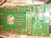
Here is a shot of the increased surface area mod I have completed. I have done the corresponding tracks on the other side. Thoughts?
Attachments
Although it won't cause problems, attaching a heatsink when soldering is unnecessary. I was concerned about this at one time but after working with Rockford's MEHSA insulators where you have to tin the backs of the transistors (and the transistors aren't harmed), I am no longer concerned about damaging a transistor when soldering it's leads.
Arrow appears to have the lowest prices on 3205s right now. Click HERE.
Arrow appears to have the lowest prices on 3205s right now. Click HERE.
I'm fixing a Thunder 2300, and I am having an issue with the bias. Both pots are turned all the way counter-clockwise, and the output FETs still heat up fast. All FETS, diodes and transistors have been checked or replaced. I am looking at four of the 3W power resistors R150, R151, R164 and R173. Does anyone know what the values are supposed to be? The colors are faded from heat. R150 & R151 are next to each other by the small toroid transformer, while R164 & R173 are across from each other on the sides of the big capacitor bank (SMPS output bank). Any help would be very much appreciated.
The resistors connected to the outputs are 0.1 ohm. The ones near the small driver transformer are 680 ohms. R173 is a 680 ohm. This is from a Rev D amp. I can't find R164.
You state that the outputs heat up quickly. Do they heat up if clamped to the sink?
If so, how much current does the amp draw with them clamped to the heatsink?
Are all insulators in place and in good condition?
You state that the outputs heat up quickly. Do they heat up if clamped to the sink?
If so, how much current does the amp draw with them clamped to the heatsink?
Are all insulators in place and in good condition?
Thanks a bunch Perry. My resistors are fine then.
I found out what it was. Someone replaced the output FETs with 100V, 50A rated ones, but they forgot to check Vth (Vgs threshold voltage). The ones they put in have a 2V typical, while the original spec IRF540 has a 3V typical. I just replaced them with IRF540. Now, with the bias pot all the way down, I'm seeing a ~3V bias for Vgs on the high-side FETs (what I expect), but only 1.3V for all of low-side FETs on both channels. This of course is giving me some bad cross-over distortion, even when I crank up the bias pot to the point where the FETs get way too hot. I'll be working on this issue today.
The insulators are in great shape. I haven't checked the current draw in idle yet, but I will.
Well, I'm stuck, Mouser are out of stock of IRF540's for the channel outputs, and they only have 9 IRF540A's left which Mr Spooney reccomends as a replacement. Do I dare buy crappy ones off Ebay??
10PCS IRF540N IRF540 TO-220 N-CHANNEL POWER MOSFETS on eBay (end time 06-Sep-10 01:47:12 BST)
These look favourite as they actually have something printed on them. I don't know anything about this topic. Can someone educate me a little on sourcing these components?
I do need to source some of those small square block capacitors, 153J100, Mouser list then as 100volts 0.015uF 5% LS 5mm, so I've ordered those today. Hope thats right...Spooney?
Oh, And I've ordered those two powersupply transistors you mentioned Q52/Q53.
And I've bought a E300 TD Mercedes Estate to put it all in. Shame its a diesel but these are well built and rattle free...nice to get some peace, I've got a Fiat X19 at the moment.
You should replace the power supply fets with IRF3205. They are more rugged than the originals and should help increase the amps reliability.
I did that Spooney, took your advice, they are in the post, but the channel fets are IRF540's, 16 of them. Any ideas? Hong Kong ones on Ebay...??
- Status
- This old topic is closed. If you want to reopen this topic, contact a moderator using the "Report Post" button.
- Home
- General Interest
- Car Audio
- MTX Thunder 2300