(warning i linked to large images for better detail to zoom)
I have this big chinese Amp that I need help with.
I have removed the output section and tested them and determined I need
to shotgun the whole section. The outputs are IRFP240.
I have also ordered a kit of 1206 smd resistors and will be replacing all of the ones I found that were open or shorted.
In the picture I am linking to here.
I know that the 7805 is also toast on one side, will replace both.
I need help determining what the drivers are and the opamps.
The manufacturer seems to conveniently scraped the numbers off of these parts.
My plan is to get the driver sections rebuilt and scope the signals before I replace a single FET.
The rails are steady @ 155vac and idle current draw seems to be about 4amps. @ 12.5 volts. I haven't given it any more power than that though.
Should I do anything else to check the Power section?
I'll add a few more pics below.
(One of them has the drivers and opamps in question highlighted in red)
More Pics
With the 3 7805s and the opto-couplers, it could be a clone of the massive amps. The massive uses 6N137s for the opto-couplers.
The massive will oscillate and produce drive signals with no outputs installed. You may have to short the positive speaker terminal to the negative speaker terminal to get it to drive the positive and negative outputs with a 50% duty cycle. Do NOT short the speaker terminals when the output are in the amp.
The massive will oscillate and produce drive signals with no outputs installed. You may have to short the positive speaker terminal to the negative speaker terminal to get it to drive the positive and negative outputs with a 50% duty cycle. Do NOT short the speaker terminals when the output are in the amp.
With the 3 7805s and the opto-couplers, it could be a clone of the massive amps. The massive uses 6N137s for the opto-couplers.
QUOTE]
Ok I will order some of those and do you have any thoughts on the driver transistors?
do you have any thoughts on the driver transistors?
Are they defaced or defective?
Try to find exact replacements. Try the following search engine:
http://octopart.com/
http://octopart.com/
Try to find exact replacements. Try the following search engine:
http://octopart.com/
LOL, I wish I knew what to look for.
Since the Output Driver transistors are defaced I have no idea what parts are usually used there. I think when the driver transistors failed they took out the opamps with them. and im sure some other SMD parts.
But, I was hoping there might be a "generally" used set of drivers betweeen the opamp and Mosfet used to switch the IRFP240's . Since they (the driver transistors) are defaced, I know that I may end up using trial and error.
But first I need a push in the right direction. My plan is (please stop me if I'm going in the wrong direction.) to replace the opamps and a sutable driver pair + all of the smd resistors and then scope the signal to see if someone here thinks it looks correct. If the signal looks wrong then maybe an additional recommendation until I get the signal chain looking correct.
Then I'll put some Mosfets in and hope i don't release the magic smoke.
I'd try BD139s and BD140s for the drivers.
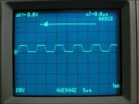
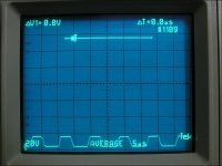
Attached are the waveforms from a Massive 3000 with the outputs removed and the speaker terminals shorted. The one with the waveform in the center of the display is the high side drive. Normally, it's riding the carrier wave so it's a bit more difficult to determine if it's a clean signal. With the outputs out, you can easily see whether it's clean or not.
Attached are the waveforms from a Massive 3000 with the outputs removed and the speaker terminals shorted. The one with the waveform in the center of the display is the high side drive. Normally, it's riding the carrier wave so it's a bit more difficult to determine if it's a clean signal. With the outputs out, you can easily see whether it's clean or not.
Attachments
This amp is a beast. What is the name of the amplifier,so that I know not to try to repair
Why do yo call this amp a beast? just curious.
oh and its from this place best i can tell.
http://www.ron-fa.cn/productShow_en.asp?bookID=217
Last edited:
- Status
- This old topic is closed. If you want to reopen this topic, contact a moderator using the "Report Post" button.
- Home
- General Interest
- Car Audio
- Amp Parts & Repair Help