LONG story short  I Shorted my aux. battery after some drifting and before I could jump out of the car the ground cable on my battery burnt completely through
I shut it down and replaced the cable and fixed the mounting
Now my system only plays the brown note
I searched and it seems the likely problem is the rca output
which I checked and the shields seem to not be grounded to the case of the deck open ohms on the meter
Is this the right test for this deck?
I've seen some fixes involving using a fused jumper between the shields and ground(Perry Babin)
What is the proper way to fix this?
Is the board burnt? Needing a resister soldered inline?
I will probably have the H.U. apart soon to check for damage
Please let me know anything you can
And I might consider shipping this to have it fixed but I don't trust a lot of these people -who would be the best to do this?
Hopefully the amps are ok -I can't see them where they are mounted so I don't know if the death blink is on
I Shorted my aux. battery after some drifting and before I could jump out of the car the ground cable on my battery burnt completely throughI shut it down and replaced the cable and fixed the mounting
Now my system only plays the brown note
I searched and it seems the likely problem is the rca output
which I checked and the shields seem to not be grounded to the case of the deck
open ohms on the meterIs this the right test for this deck?
I've seen some fixes involving using a fused jumper between the shields and ground(Perry Babin)
What is the proper way to fix this?
Is the board burnt? Needing a resister soldered inline?
I will probably have the H.U. apart soon to check for damage
Please let me know anything you can
And I might consider shipping this to have it fixed but I don't trust a lot of these people -who would be the best to do this?
Hopefully the amps are ok -I can't see them where they are mounted so I don't know if the death blink is on
Ok I swapped in an old Alpine -same plug")
and the amps are ok
I like the 7998 and if I can't fix it I will get it done
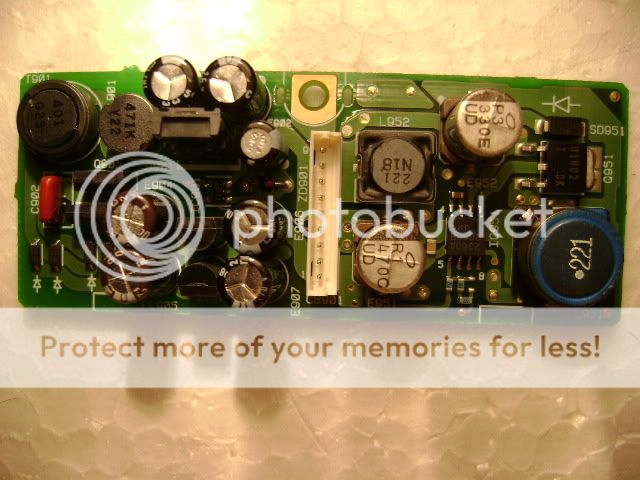
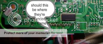
So far I pulled the upper board and tried to back-trace the ground -I don't see any obvious problems -except that it appears all 3 rca grounds are adjacent to the main ground jumper to the frame but not connected -should they be? There are a few paths to trace but what should I be looking for -I'm trying to eliminate curcuits but hard to tell what does what
 [/IMG]
and the amps are ok
I like the 7998 and if I can't fix it I will get it done
So far I pulled the upper board and tried to back-trace the ground -I don't see any obvious problems -except that it appears all 3 rca grounds are adjacent to the main ground jumper to the frame but not connected -should they be? There are a few paths to trace but what should I be looking for -I'm trying to eliminate curcuits but hard to tell what does what
7998R?
If it has an external power supply, the open ground may be there.
The fused jumpers aren't a permanent solution. They're used to temporarily repair the open shield. The shields on higher quality head units are connected to chassis ground but it's often done very carefully to minimize the likelihood of producing engine noise due to ground loops inside the head unit. Ideally, you want to find the point that's burned and repair the open connection at that point.
I don't have an "R" -is there a difference?
The plug inside the external ps is grounded to the h/u frame via the black wire with 1 ohm resistance -no visable damage
The ground terminal has ~3 ohms to the board screw plate
I can test curcuits but my knowledge is limited
Do I trace the ground wire terminal back or can I test the board via "pin a to pin b"?
I assume I'm looking for a fried resistor that breaks the ground curcuit
I'm trying my best to figure this out in between everything else I have to do all day
Thank you for taking the time to respond
I don't know if the R version is different.
I don't know if there will be a resistor or fuse in the shield ground. On the schematic (R version), I don't see any components between the shield ground and the other grounds. It appears that shield ground is tied directly to chassis ground but I'm not sure where. On the schematic, they appear to tie together near a 100uf, 10v capacitor (E208?).
If the shield ground is open, it's likely to be an open trace (likely where it gets narrow) or a burned via (feedthrough) that connects two traces on opposite sides of the board. Brush/lightly scrape any parts of the trace that appear dark or discolored. If the solder mask (or the trace) lifts, confirm that the trace isn't open.
FINALLY the forum is back!
I have been checking in every hour like a fiend -need my system back
OK now back to the matter at hand
It seems there are 3 block fuses?, not sure how to ID these, between the shield grounds and the main ground terminal that have continuity on one side (to the shield) but not the other
I think if I can replace these all will be right in the world
ok I finally got time to look at this again
E208 and the cap. are next to a TDA7402 IC signal processor
could it be bad? and is there a simple pass/fail test to check?
I read through the datasheet and it's a pretty complex unit
http://www.datasheetcatalog.org/datasheet/SGSThomsonMicroelectronics/mXuzruz.pdf
I see no visual damage anywhere
pin#19 is designated as ground and it is not grounded to the case
I am trying to back trace from the main ground location back to see where there is a break
My understanding of the circuits is limited
It seems like there should be a breakthrough soon I am tracing all the ground paths
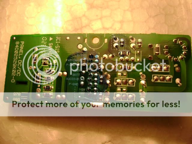
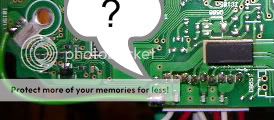
There may be something missing (where the point is) as there are two via spots but nothing connected -the back is bare traces looks a little strange
E208 and the cap. are next to a TDA7402 IC signal processor
could it be bad? and is there a simple pass/fail test to check?
I read through the datasheet and it's a pretty complex unit
http://www.datasheetcatalog.org/datasheet/SGSThomsonMicroelectronics/mXuzruz.pdf
I see no visual damage anywhere
pin#19 is designated as ground and it is not grounded to the case
I am trying to back trace from the main ground location back to see where there is a break
My understanding of the circuits is limited
It seems like there should be a breakthrough soon I am tracing all the ground paths
There may be something missing (where the point is) as there are two via spots but nothing connected -the back is bare traces looks a little strange
well it seems that there are only 2 ground paths on the upper board
the first dead ends around the plate caps. and the rca plugs
the other goes through the crossover select switch(2-way or 3 -way) and on to the lower board through a ribbon
I guess I will have to pull the lower board out and check it
again everything seemed to work except the audio(buzz of death)
it's just hard to tell which circuits are for the audio section
I'm trying to figure this thing out but feel lost
Thank you Perry Babin!
ok I should follow(read) your instructions better
I was tracing the chassis ground instead of the shield ground
I am still learning as I go and finally took my time to understand what you were telling me and what I was doing wrong
The 100uf near E208 does have a leg that connects to the rca shield
I traced one direction to the large fixed 32 pin plug that goes to the lower board labeled "TUG" on the corresponding pin on the lower board
I don't have continuity from the pin(blade) to the bottom board
It seems the pin is bad inside -It's good from the board to a slot on the side of the plug but not from the slot to the blade
How do I fix the pin?
I don't want to start prying on the plug too much to see if the upper blade holder can be slid off but that would be easier than desoldering the whole thing
I hope you hadn't written me off as a total waste of time
I just wasn't able to focus enough attention to this lately
Thank you for getting me this far -I may be able to save this one!
Upon further examination there are 3 burned links inside the 32 pin plug
1. "TUG"
2. "3YG"
3. "AGND"
The only way is to connect to the other side of the board and wrap the wires around to connect to the top board
It seems I have continuity between "3YG"+"TUG" is that right? or are the burned leads in the plug touching?
Well I put it all back together and... no more buzzing!...
Wait a minute no sound at all -heard faint music at FULL volume -I didn't know it went to 35 as I never had to turn it up that high before
What else is blown? -I wish I could just get new boards to put inside rather than troubleshooting 1 thing at a time
Back to the old drawing board
- Status
- This old topic is closed. If you want to reopen this topic, contact a moderator using the "Report Post" button.
- Home
- General Interest
- Car Audio
- Alpine 7998 Trouble?