Hey, this is my first post on the forum but I've been around for a little while reading and learning quite a bit, especially from Perry and his tutorials. I have been getting interested in electrical circuits lately, especially with car audio but never had the desire to tear my fully functional amps apart until now. My amp to my components went into protect mode so I figured I'd fix it myself. Its a 300/4 from JL and I'm only using the two front channels so the bad channel wasn't hard to find. I only replaced the fets and after hooking it back up, they took a crap again after 20 minutes or so of playing music. I'm gonna be replacing those again today, along with some resistors. I'm also gonna resolder the driver resistors, check zener diodes on the driver board, and also replace the 5 watt .1 ohm resistor. Is there anything else I should do to make sure these would go on me again? What even causes these JL amps to go through output fets so much? Thanks in advance guys.
If all of the LEDs are lit on the driver boards and it was producing clean audio, the driver board components are likely OK.
The solder connections on the resistors marked 473 (on the driver board) should be resoldered (actually, add new solder, desolder and resolder). The failure of the solder connections on those resistors generally causes either distorted output or the amp will go into protection.
I've never seen the large 0.1 ohm resistors fail. They're likely OK. You can check them after you remove the shorted FETs.
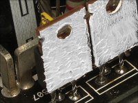
When you reassembled it, did you remove the old heatsink compound and replace it with new compound? When you add new compound, only apply it to the transistors. Don't apply too much (no more than on the transistors in the attached image). When the transistors are clamped, make sure that the compound is displaced evenly around the entire perimeter of the transistor.
When you adjust the bias, you'll either need to insulate your probes so they don't short on the busbars or you'll have to touch the probes to the test points on the bottom side of the board.
When adjusting the bias current, have the transistors clamped to the heatsink and have a 10 amp fuse in the B+ line. Turn the bias pot slowly.
The solder connections on the resistors marked 473 (on the driver board) should be resoldered (actually, add new solder, desolder and resolder). The failure of the solder connections on those resistors generally causes either distorted output or the amp will go into protection.
I've never seen the large 0.1 ohm resistors fail. They're likely OK. You can check them after you remove the shorted FETs.
When you reassembled it, did you remove the old heatsink compound and replace it with new compound? When you add new compound, only apply it to the transistors. Don't apply too much (no more than on the transistors in the attached image). When the transistors are clamped, make sure that the compound is displaced evenly around the entire perimeter of the transistor.
When you adjust the bias, you'll either need to insulate your probes so they don't short on the busbars or you'll have to touch the probes to the test points on the bottom side of the board.
When adjusting the bias current, have the transistors clamped to the heatsink and have a 10 amp fuse in the B+ line. Turn the bias pot slowly.
Attachments
I got the two 47k ohm driver resistors resoldered and the old output fets out today and it went a lot easier than the last time. While I have a thread going I would like to clear a few things up. To adjust the bias im going to turn the pot by the driver board and check the reading where the two holes are by the fets labeled bias, right? As I understand, this is changing the resistance of the signal going to the fets. Also, where can I find some more information on how the path the signal takes through the amp? From your tutorial Perry, I have read that after leaving the voltage amplifier the signal would go to the driver transistors, followed by the output transistors before the speakers. Im lost on how it gets here from the transformers. Other than this, you have a great intro to repair and I plan on gettting your full tutorial eventually as im in the middle of buying a house and my job is becoming more uncertain as the days go on. But thanks for all the help so far.
I got the two 47k ohm driver resistors resoldered
**** 2 per driver board?
and the old output fets out today and it went a lot easier than the last time.
**** They'll drop out easily if you add enough new solder to allow the soldering iron to heat all 3 terminals when you lay the tip of the iron across them.
While I have a thread going I would like to clear a few things up. To adjust the bias im going to turn the pot by the driver board and check the reading where the two holes are by the fets labeled bias, right?
**** Yes. This file shows the relationship of output to driver board.
http://www.bcae1.com/temp/jlaudio300slash4driverboardandoutputs01.swf
As I understand, this is changing the resistance of the signal going to the fets.
**** No transistor switches on the instant that a tiny fraction of a volt is applied to it. This type of FET typically takes just over 3v to start to pass current. If the outputs aren't at (or very near) that threshold (~3v), the drive circuit will have to be infinitely fast to swing from 0v to 3v to prevent distortion. The bias sets the voltage so that the outputs are just beginning to conduct. The voltage across the test points is the voltage from one output's source to the other output's drain. It's probably ~4mv.
Also, where can I find some more information on how the path the signal takes through the amp? From your tutorial Perry, I have read that after leaving the voltage amplifier the signal would go to the driver transistors, followed by the output transistors before the speakers.
**** It varies from amp to amp but that's essentially correct, preamp level in >> differential amplifier >> voltage amplifier stage >> drivers and then outputs.
Im lost on how it gets here from the transformers.
**** Audio doesn't pass through transformers on most car amps.
I don't think I made any statements about the condition of the boards if the LEDs were 'not' lit.
I clearly want to be corrected if I'm wrong but you should quote the part of the post that's in error and then state precisely why it's wrong.
You probably would have received a different response if you hadn't just told someone else they were wrong without stating why.
http://www.diyaudio.com/forums/showthread.php?postid=1889140#post1889140
Well I had it fixed and plugged it in in the car with a smaller fuse in the distro block to set the bias and the power stage started humming and the protect light lit back up. After cutting off the power, it seems that the power transistors got hot somehow. One of them appeared to have gotten hot enough to darked the solder on the bottom of the board. Im not sure what caused this but im going to check it out more tomorrow and let ya know what I find out as I havent got to check the transistors yet.
No Perry, I do not have a power supply at all. I just checked the transistors and all my power fets are bad, along with the output fets I just replaced. I am short a couple irfz44s so Im going to reorder and I plan on building a power supply before they arrive. The irfs44 is tested the same as the irf540, right?
Ok, they are definitely all junk then. I ordered some more and found a simple power suppy i can make with a few parts from radioshack. Ill try and add a way to adjust the current while im at it. Ill let you know when the new parts arrive. I did find it odd that the outputs are bad, since all the lights on the board were lit when i cut the power.
Perry, I just got done checking components on the amp and now im baffled. The front left channel has one shorted fet, and one good fet. The front right channel, which was the initial problem, has both fets shorted. The rear left channel has a shorted fet and a good fet, and the right rear channel is still good. All power fets are shorted and the smaller transistors between the output fets are also shorted. I know I have much to learn but still I dont understand how this is possible. Have you ever seen something like this?
Also, I think Ill be snagging up your tutorial tonight. Then knowledge you have is incredible.
Also, I think Ill be snagging up your tutorial tonight. Then knowledge you have is incredible.
When you powered it up, were all of the transistors clamped to the heatsink?
Was the insulator between the transistors and the heatsink in place?
Were the mating surfaces between the transistors/insulators/heatsink free of foreign material (except for the heatsink compound)?
Was the insulator between the transistors and the heatsink in place?
Were the mating surfaces between the transistors/insulators/heatsink free of foreign material (except for the heatsink compound)?
I cleaned the heatsink area off and then added some compound i use for computer processors to the backside of the transistor. Could the driver transistors have caused this? I tested them from the bottom of the board and they were shorted. Im gonna check into it a little more in a bit.
- Status
- This old topic is closed. If you want to reopen this topic, contact a moderator using the "Report Post" button.
- Home
- General Interest
- Car Audio
- JL 300/4 - First Amp Repair