Lightning Audio x1.2000.1D
2000 watt Class D
Power Supply, Output, Driver Chip, Driver transistors Blown. This amp is similar to the 1000watt class D but almost everything is doubled.
I found IR2010 bad, all driver transistors replaced and then I changed the power supply FET out for RFG70N06 and output to FDP39N20 I started with one FET in each stage to test amp power on and idle current all went well. Sine wave at low power out put to dummy load, ok. Installed the rest of the FET and at high volume the inductors vibrate, hum and the amp goes into protect, recovers and protects again. I know in class D replace only with same FET but I happen to have these in stock and the values were almost on except Gate Capacitance, but gate resistors were well in range. At idle power FET don't seem to get hot or draw excess current, idel current is 1A. I won't get my scope back until end of next week to see wave form but I was looking for any ideas.
Power Supply FQP65N06
Gate Resistors 56 ohm
Driver Transisters :
KTC1027 NPN 800mA
KTA1023 PNP 800mA
Driver Board uses TL494CN
First the power supply I put in RFG70N06 in place of FQP65N06
FQP65N06 RFG70N06
Volt 60v 60v
Rds .016 .014 Resistance
Ciss 1850pF 3000pF Input Capacitance
Tondelay 20ns 12ns
Current 65A 70A
Output 45N20B
Gate Resistors 1ohm
Driver Chips IR2010,HEF4070BT
Replaced output from 45N20B to FDP39N20
SSP45N20B FDP39N20
Volt 200V 200v
Rds .065 .066
Ciss 3300pF 1640pF
Tondelay 45ns 30ns
Current 35A 39A
They may have been using the gate capacitance to determine deadtime. If that's the case, and there are 100 ohm resistors in parallel with a diode (in the drive circuit feeding the gates of the outputs), you may be able to make the sub outputs work by increasing the resistance to 200 ohms. I'm using the 1000 as a reference, not the 2000. I've never worked on the 2000.
Could you read the 2010 clearly on the IC? I've seen (and used) the 2110 in some of their amps but never the 2010.
Could you read the 2010 clearly on the IC? I've seen (and used) the 2110 in some of their amps but never the 2010.
There is no marking on the output driver I typed it wrong, I assume it is a 2110 as in your picture of the 1000d amplifier the board looks similar.

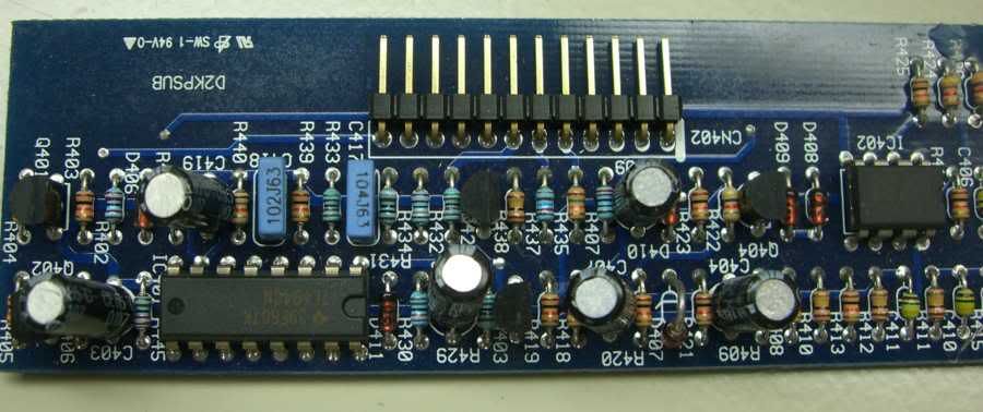
This is the driver transistors section of the board.

This is the driver Board


This is the driver transistors section of the board.
This is the driver Board
I have a strike 1kw, they had low idle current compared to others like 1A. I might have a remote for an X I forget what sizes was for though.

These are the readings at the Rectifiers.
No They aren't the same. Voltages are different too.
I switched the driver board(TL494) in the power supply section, with known good and still same. Driver transistors are separate from this board.

No They aren't the same. Voltages are different too.
I switched the driver board(TL494) in the power supply section, with known good and still same. Driver transistors are separate from this board.
Is this the power supply?
The scope says it's 150v+ p-p. I assumed that it was the outputs (even thought the frequency was lower than it should be for the outputs).
The top waveform isn't too bad for the power supply but the bottom one isn't right. I would suspect that you have defective drivers. What does the gate drive waveform look like on the emitters of the 4 a1023 driver transistors?
Found a bad connection on the driver transistor that I replaced and didn't see.
Fixed that
Power Supply New Wave Form

During testing amp works ok at low volume but when I turn it up it goes into protect. Following picture is of speaker output waveform just before protection power off.

Input voltage seems ok 90amp cascade power supply and dosn't drop below 14volts, 30amp draw before protection. I am using a 4ohm 400watt resistor for load. Still trouble shooting.
Fixed that
Power Supply New Wave Form
During testing amp works ok at low volume but when I turn it up it goes into protect. Following picture is of speaker output waveform just before protection power off.
Input voltage seems ok 90amp cascade power supply and dosn't drop below 14volts, 30amp draw before protection. I am using a 4ohm 400watt resistor for load. Still trouble shooting.
If you let it idle for 10-15 minutes (no load, no input signal), does it (outputs/heatsink) remain at room temperature?
If you run it to clipping without a load, does it shut down?
If you run it to clipping without a load, does it shut down?
power ( lightning audio )
hello, iam a new member. am interested to join this sites because i have same problem with this power amp and ineed to know about sparepart, can u help me to get the sparepart i need : FQP 65N06 and SSP 45N20B. may I buy from u. tanks for the information.
hello, iam a new member. am interested to join this sites because i have same problem with this power amp and ineed to know about sparepart, can u help me to get the sparepart i need : FQP 65N06 and SSP 45N20B. may I buy from u. tanks for the information.
If you can't find a source closer to Indonesia, try the following:
http://octopart.com/parts/search?q=FQP65N06&js=on
http://octopart.com/parts/search?q=SSP45N20B&js=on
http://octopart.com/parts/search?q=FQP65N06&js=on
http://octopart.com/parts/search?q=SSP45N20B&js=on
If you can't find a source closer to Indonesia, try the following:
FQP65N06 - Octopart
SSP45N20B - Octopart
hello perry, sorry can u help me to find out the IC, I can not read the number, because its blank ( did in purpose ), how can i found it? tanks for helping me.
I believe the driver IC is an IR2110. The 2110 worked in the 1000 watt amp. I'm assuming it's the same in this amp.
I believe the driver IC is an IR2110. The 2110 worked in the 1000 watt amp. I'm assuming it's the same in this amp.
Tank you very much perry, for helping me. see u😉
hello again perry, sorry iam confuse about the driver IC IR2110, when i search part, there are alot of IR2110 with letter behind, such as IR2110PBF, IR2110S and many, so wich one should i choose, it is ok if i choose IR2110 without letter behind, tankyou, how stupid iam.😕
S = surface mount
PBF = lead free
It doesn't matter (to the circuit) if it has lead or not.
ok tankyou, maybe i should try to put the IC and i will tell you later it is work or not, ok by
- Status
- Not open for further replies.
- Home
- General Interest
- Car Audio
- Lightning Audio 2000watt Class D