 Hi everyone
I'd like to repair this amplifier. I fixed power supply succesfully,but
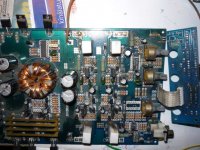
the amplifier hasn't work yet.It is too complicated,that's why I need the shematic diagram. All the transistors are ok. Main components are
the following:2xTIP35/36, 2xBD911/912, 2xLF347.
Is anybody can help me?
Thanks in advance.
does this pic help
An externally hosted image should be here but it was not working when we last tested it.
Hi Perry
Thanks for Your answer.
I measured some voltages.
1.The 12V drop down about 8V when powered on with remote control, and it takes more then 2 amps. (I've to mention that I
try it with a current limited power supply) By the way I have a question. About how many amps are expectable normaly without
AF driving? Perhaps is it more than 2amps?
2.So there are +/-11V on rails.
3.Inotice that the NPN part of the amlifier (TIP35 and their drivers
BD911) get warm, but the other side (PNP) stand (or stay?) cold.
4.There is DC level at the speaker output!(about 1,6 V)
These happen both 2 chanels. I think that it is important.
By
Thanks ben04srt. It helps.
ha8wx:
1. An amp this small shouldn't draw more than 2 amps at idle. What is the current rating of your power supply?
2. What DC voltage do you have on pins 4 and 11 of the op-amps? Touch your black meter probe to a non-bridging speaker terminal when measuring the voltage.
3. Generally, if there is a problem causing excessive current flow which is causing one output in a channel to overheat, that problem will cause the other output in the same channel to overheat unless the output is shorted or is being driven fully on. I'll assume that none are shorted. With the black meter probe on the emitter of the output transistor and the red probe on the base of the same transistor, what is the DC voltage for each of the 4 output transistors. Note whether the transistors are NPN or PNP.
4. With your black meter probe on a non-bridging speaker terminal, do you read positive 1.6v when the red probe is touched to either of the bridging speaker terminals (ch. 1+/ch. 2-)?
")
HI
My power supply can achieve max. 3 amps.
At the output there is positive 1,6v
The voltages between B-E are 0,65 V at TIP35 so they are open.
At TIP36 are 0,4V
The rail voltages are +/-11v instead of +/-28v, and +/-3v are
on 4 and 11 pins of the op-amps.
I'll send a photo about the PA latter.
My power supply can achieve max. 3 amps.
At the output there is positive 1,6v
The voltages between B-E are 0,65 V at TIP35 so they are open.
At TIP36 are 0,4V
The rail voltages are +/-11v instead of +/-28v, and +/-3v are
on 4 and 11 pins of the op-amps.
I'll send a photo about the PA latter.
Hi
My next intention is to separate power supply section from the
audio section. I want to decide either the power supply or audio
section is failed.
Do You think it is a good metod?
I have 2 chance to do this:
1, to cut the PCB or
2, remove all the components from the rails.
As i don't want to cut the PCB i choose 2-nd one.
Hi Perry
Answering to Your question : as I mentioned transistors get hot in
a few second
after power on. It draws overcurrent. I think this becouse the power
supply limits at 2,1 Amps. It happened always, either the dummy
load was conected or not.
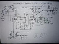
In the meantime Idrew the circuit diagram of the power supply.
It is not 100% complete.
Well I removed all the components from the rails except capacitors
(2200uF) and feedback resistors. When I applied B+ and power on
the rail voltages was +/- 28,1 Volts. Then, the idle current was
0,35A at B+. After that I applied 2X 24V 5W bulbs at dummy load.
Than the current was 1,5A and voltages +/-28V.
I was happy. It ment that the power supply section is OK.
Answering to Your question : as I mentioned transistors get hot in
a few second
after power on. It draws overcurrent. I think this becouse the power
supply limits at 2,1 Amps. It happened always, either the dummy
load was conected or not.
In the meantime Idrew the circuit diagram of the power supply.
It is not 100% complete.
Well I removed all the components from the rails except capacitors
(2200uF) and feedback resistors. When I applied B+ and power on
the rail voltages was +/- 28,1 Volts. Then, the idle current was
0,35A at B+. After that I applied 2X 24V 5W bulbs at dummy load.
Than the current was 1,5A and voltages +/-28V.
I was happy. It ment that the power supply section is OK.
Attachments
- Status
- This old topic is closed. If you want to reopen this topic, contact a moderator using the "Report Post" button.
- Home
- General Interest
- Car Audio
- Earthquake PA-2050C shematic