hello,
i've picked up a defective amp to fix it and i've got in to this issues that i don't manage to fix it
it's a classic amp ( about 800w rms bridged) build on TL494 and irfz 44n (8 of them for each channel - 2 total) ... every time i'm powering on the amp the, voltage drops to 6 volts and 4 of the irfzs - right side- are heating up...i've have replaced them with another 4 new ones but still same result....i don't have the schematics for the amp and i've tried to do a revers engineering for the pcb but is kind of hard to follow up the circuit
.any suggestion will be more then welcomed!
thanks in advance
Check the 4 gate resistors of those FETs. Also between the gate resistors and the TL494, there is possibly a defective PNP transistor. If there are 2 transistors between the resistors and the 494 they both may be defective.
Don't power it back up until you replace the transistor or resistors. You may want to put an automotive headlight bulb in series with your powere wire to act as a current limiting resistor.
Don't power it back up until you replace the transistor or resistors. You may want to put an automotive headlight bulb in series with your powere wire to act as a current limiting resistor.
Can't find a schematic.
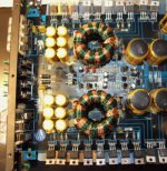
A picture is pretty much useless at that level of detail, but one thing I can tell, the layout is symmetrical.
If you go through the circuit with a DVM testing resistances and doing diode tests in both directions across the transistor pins, you should be able to identify the problem area by comparison with the side that is OK.
w
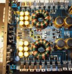
Start by figuring out which of the 4 transistors are connected to the 4 gate resistors of the set of FETs that are getting hot. There are now 2 yellow rings in this picture. If one of the 4 transistors inside the rings connect to the gate resistors of that set. Change it. Did you check the gate resistors? The yellow rings are located to the west and to the south of the 494.
Attachments
...sorry for late replays but since i'm new to this forum they have to check my messages every time i'm posting a replay..
k..here what i did by now: i've used a 12v bulb in series with the +12 , that was a great idea , the IRFs are not heating up that much..and...what i've noticed is that when i'm conecting the + wire the light on the bulb is fade( the voltage drops to 7V ) and after about 8-10 secs the toroid on the side that the IRFs are heating starts to make a zooming noise and after the 10 secs the voltage drops one more time to 3 volts and the light on the bulb gets brighter!!
can the toroid be broken or anything else??
i'm trying now to figure out the path for the +12 on the back of the PCB and see if there is no shortage or anything...
i found the transistors related to the FETs, is a pair of A1013 and C2383..and they are ok too...when i said i've checked all the transistors on the pcb actually was i did was to pull out each one of them and measure it...and all are ok..i also have replaced the 494 but still is doing the same thing...
Take a DVM and check some spot voltages around the circuit, comparing the working channel to the faulty one. Use the bulb trick.
This is a lot quicker than pulling components, and there's less risk of doing mechanical damage, but don't let anything cook while you poke around.
w
This is a lot quicker than pulling components, and there's less risk of doing mechanical damage, but don't let anything cook while you poke around.
w
k..here it is what i dig up...
the voltage drops only when the remote and the +12V from bat. are connected together...otherwise if only the remote or the bat 12v is connected nothing goes wrong... i've fallowed the +12 remote path and that supposed to give a 12V to the 10 pin of the TL 494 if i'm not wrong ...on the board before the TL there is a resistor divider followed by a pair of transistors... i'm getting the 12v as supposed on the resistor but after him drops to 0.6v...and therefore no 12v for the TL ci....12V bat not connected at this time..
the voltage drops only when the remote and the +12V from bat. are connected together...otherwise if only the remote or the bat 12v is connected nothing goes wrong... i've fallowed the +12 remote path and that supposed to give a 12V to the 10 pin of the TL 494 if i'm not wrong ...on the board before the TL there is a resistor divider followed by a pair of transistors... i'm getting the 12v as supposed on the resistor but after him drops to 0.6v...and therefore no 12v for the TL ci....12V bat not connected at this time..
The voltage is dropping because something is pulling it down.
Pull the FETs like the Idiot says.
Presuming they are not faulty, the voltage on the gates is incorrect. They barely load the preceeding circuit so it will not notice they're gone.
Now check the voltages on the pads where the FETs were connected. Check the same voltages (pins) on the corresponding working FETs. You should find a difference, if not report back.
If the voltage is incorrect, this is the cause of the overheating. The task now is to determine which component or components are at fault. The first place to look is the component or components which are connected to the gate. Compare spot voltages on these components with the working ones.
Now compare spot voltages on the components which are connected to these components. If you can't see the tracks you can just ckeck for continuity to other components with a DVM with the circuit switched off. Just go round all the pins. Work your way back through the circuit. When you find a place where the voltages are the same, or very close, you can stop.
Now you can either replace all the components from the 'good' point to the gate pad or track down the ones which are faulty, because they lie between the 'good' point and the gate.
w
..progress to report ")
i replaced 2 transistors that supposed to fed 12v to the TL... checked all the pins and had right voltages, put back the FETs each side at the time and got the same voltage drop , so i have removed the rectifiers and i'm getting a 50V AC after the toroids...i will double check the rectifiers again ,maybe even replace them and pull out and check all the power transistors...
i replaced 2 transistors that supposed to fed 12v to the TL... checked all the pins and had right voltages, put back the FETs each side at the time and got the same voltage drop , so i have removed the rectifiers and i'm getting a 50V AC after the toroids...i will double check the rectifiers again ,maybe even replace them and pull out and check all the power transistors...
- Status
- This old topic is closed. If you want to reopen this topic, contact a moderator using the "Report Post" button.
- Home
- General Interest
- Car Audio
- 12 volts drops to 6 when amp is powerd on