Hello! Whoaa, my first post here.
I have a problem repairing Ground Zero 24 volt amp. First I found power supply fets (IRF3415) shorted, their driver transistors (2SA1023, now replaced with 2SA1124) shorted and TL494 controller pins 10 and 11 shorted and between pin 8 and 10 was 15 ohms. There was also a couple of shorted output transistors Snaken 2SA1693 and 2SC4466 at two channels, other two channels were probably never used.
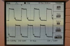
Parts are replaced, and I also replaced gate resistors of supply fets, and added 1k pull down resistors from gate to ground. Attached is scope picture of voltage at the gates of supply fets. When powering it up at first there is about 300 mA current draw slowly rising, at the moment of picture there is almost a 5 A draw and rising. If remote is not pulled away the fets get too hot and will fail. All this when amp section voltage rails are cut off so no load for power supply.
Any ideas? More pictures will be sent if needed.
PQ
I have a problem repairing Ground Zero 24 volt amp. First I found power supply fets (IRF3415) shorted, their driver transistors (2SA1023, now replaced with 2SA1124) shorted and TL494 controller pins 10 and 11 shorted and between pin 8 and 10 was 15 ohms. There was also a couple of shorted output transistors Snaken 2SA1693 and 2SC4466 at two channels, other two channels were probably never used.
Parts are replaced, and I also replaced gate resistors of supply fets, and added 1k pull down resistors from gate to ground. Attached is scope picture of voltage at the gates of supply fets. When powering it up at first there is about 300 mA current draw slowly rising, at the moment of picture there is almost a 5 A draw and rising. If remote is not pulled away the fets get too hot and will fail. All this when amp section voltage rails are cut off so no load for power supply.
Any ideas? More pictures will be sent if needed.
PQ
Attachments
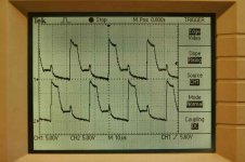
The gates should be pulled closer to ground on the falling edge of the waveform.
Can you post photos of the waveforms on pins 9/10, the base of the driver transistor, the emitter of the driver transistor and the gate (if it is not the same as the one you posted). Ground your scope probe to the ground terminal of the amp when capturing the waveforms.
I think the problem is likely going to be the driver transistors.
Thank you for answering!
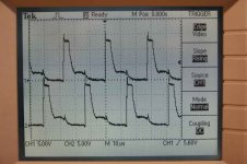
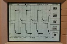
Pic 11 shows outputs of TL494, probe 1 is pin 10, probe 2 is pin 9.
Pic 12 shows emitters of driver transistors, probe 1 is on transistor which is connected to pin 10 of TL494.
Earlier picture was the gates of fets, and probe ground was at GND terminal of amplifier.
There is also four 1N4148 signal diodes between emitters and bases of driver transistors. I find it odd that there is two diodes per transistor, one this direction, other is opposite direction. Should they really be 1N4148's?
Attachments
This problem (drive signal not going to ground) goes back to the 494. You could try using lower value pulldown resistors on pins 9 and 10 (minimum of ~300 ohms) but I really think the drivers are the problem. If you look up the datasheet for the drivers, you can see that they have a very low current rating. If the current for the drive circuit is near the current rating for the drivers, the DC gain will be VERY low and can cause this problem. The original transistors are rated for much higher current. (50ma vs 800ma).
If you have 2N6491s on hand, try installing them in place of your drivers. The pin configuration is reversed so you'll have to install them facing the opposite direction in the board. If you have MPSA56s, you can use them for testing if you reverse legs 2 and 3.
If you have 2N6491s on hand, try installing them in place of your drivers. The pin configuration is reversed so you'll have to install them facing the opposite direction in the board. If you have MPSA56s, you can use them for testing if you reverse legs 2 and 3.
Hello!
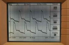
Attached pic shows what happens at gates of power supply FET's. Now there is 470 ohm pull down resistors to supply gnd between MPSA56 and gate resistors. There is no pull down resistors at pins 9 or 10 at PWM controller TL494, before MPSA56's, this is just like original.
This is when amp draws 1,1 amperes and it keeps rising, no DC voltage on channel outputs and seems that +- 15 volts at op amps is ok. No output transistors get hot or warm, power supply FET's heats only a bit.
Is this ok? Thank You in advance!
PQ
Attachments
Added 820 ohm resistors from pins 9 and 10 to gnd, and took out gate resistors between MPSA56's and gnd, see pic. Better?
The 24 volt line is feeding a 220 ohm / 1 watt resistor, after that there is a 16 V zener diode to gnd and this goes to TL494 pins 8 and 11, here I measure about 16,6 volts when supply voltage is 27,3 V. I have understood that fet conducts at saturation even when it is conducting higher voltage than there is on gate, correct?
I took out MPSA56's and replaced them with ones with longer legs, should help with some cooling.
Thanks!
Attachments
They regulate the voltage to prevent having more than 20v drive going to the gates. Above 20v (voltage from gate to drain), the FETs could be damaged.
As long as the Vgs is 10v or more, the FET will be fully on (saturated), no matter the circuit voltage (Vds).
The drivers will probably run hotter with longer leads. With short leads, they can sink some heat to the board. No matter the length of the leads, they should be reliable.
Are the FETs running cooler with the pulldown resistors on 9 and 10?
Hello and Thank for your help!
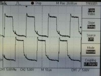
This amp is now playing, pic shows gates of power supply FET's. They get warm but not too much. MPSA56's get quite hot, can touch them for few seconds though.
Still it draws about 3 amperes when voltage is 27 V and with no signal, after ten minutes of playing easy background music. This is too much I think.
No other transistors get hot, only warm. Sound is ok, as far as cheap amps usually can provide. +-15 volt line is steady, just as +-36 volt power supply lines, no noise or other oddities there.
PQ
Attachments
- Status
- This old topic is closed. If you want to reopen this topic, contact a moderator using the "Report Post" button.
- Home
- General Interest
- Car Audio
- Ground Zero 24 volt amp repair