Okay I am going to come right out and say it, I am an idiot!!! I was in a hurry and too excited to use the correct precautions, which would have saved my amp.
I accidentally wired the 12v power to my Rockford Fosgate 5005 backwards, meaning I connected the battery + to the amps - and so on. I was just testing the amp before installing it my car and unfortunately I didn't have a fuse in place. Stupid, stupid, I know. It blew two mosfets and I replaced them already, and what a joy that was. I couldn't get them to solder back to the Mehsa board so I built braces to hold them down using the exsiting screws.
Everything looks good so I a hooked it up the right way and I even used a 15 amp fuse. However, I still have a problem with the amp. All it does is blow the fuses when I turn the key and power goes to the REM wire. The fuse doesn't blow until the REM power turns on. It will also blow a 20 amp fuse.
What do I need to do now?
If you could not get the transistors to solder down to the strip, how did you get the old ones off of the strip? If you pulled the old ones off with a pair of pliers, you have destroyed the strip. Chances of getting a good heat conductive surface is slim to none and slim is on vacation. One of several things could be causing it to blow the fuse when it is powered up. 1 shorted output transistors. 2 Bad driver transistors in the supply.
Call Rockford and see if they will sell you the fets mounts on a MESHA panel I have heard they might sell you the part, Or follow Perry's directions on how to rebond the devices properly with a mini torch. He has a pretty neat way of doing it.
You most probably also blew out the fet drivers on the board they will be SMD transistors, so they will be very small and located in two pairs near the PWM chip. They are usually MPSA-06 and MPSA-56
Plus you might have also damaged the PWM chip along with the protection op-amp located nearby. This is about the worst case I can think of based on your info or what possibly could be damaged, and its pretty much all of the power supply circuitry involved with the 12 volt side.
Now I am basing this on a few hundred experiences with the exact same issue... So you not alone in having done this thing you did to your amp..... Good luck and search this site for Perry's MESHA articles there are already posted here just look em up....
")
You most probably also blew out the fet drivers on the board they will be SMD transistors, so they will be very small and located in two pairs near the PWM chip. They are usually MPSA-06 and MPSA-56
Plus you might have also damaged the PWM chip along with the protection op-amp located nearby. This is about the worst case I can think of based on your info or what possibly could be damaged, and its pretty much all of the power supply circuitry involved with the 12 volt side.
Now I am basing this on a few hundred experiences with the exact same issue... So you not alone in having done this thing you did to your amp.....
Good luck and search this site for Perry's MESHA articles there are already posted here just look em up....It almost sounds like you got the transistors successfully connected without destroying them and that the remote being applied causes them to kick on and ground to the chassis and pop your fuse. Is it possible their metal tabs are grounding directly to the heat sink somehow? Did you use mica, kapton, or silicone insulators to keep them from contacting the sink?
I did use a torch (radio shack model) to remove the old mosfets which did not damage the board at all. Most of the solder was removed and left a flat surface for the new ones to mount to. I built a metal brace to hold the new ones down as shown in the pictures. I tried to remount them but the solder just will not stick to them.
Can someone point out the componets on my picture that "1moreamp" was talking about here:
and do I need insulators listed below for my aplication?
Can someone point out the componets on my picture that "1moreamp" was talking about here:
You most probably also blew out the fet drivers on the board they will be SMD transistors, so they will be very small and located in two pairs near the PWM chip. They are usually MPSA-06 and MPSA-56. Plus you might have also damaged the PWM chip along with the protection op-amp located nearby.
and do I need insulators listed below for my aplication?
Is it possible their metal tabs are grounding directly to the heat sink somehow? Did you use mica, kapton, or silicone insulators to keep them from contacting the sink?
Attachments
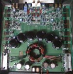
Morning, Put your finger on the RCAs and then slide you finger directly south towards the big caps. Just in front of the two center black caps.
The last chips and the 4 transistors located in a row are what I was talking about.
This is you power supply control section. The 4 little transistors side by side should be your fet gate drivers.
How you can tell is that each set are connected together as pairs, and one circuit trace goes to one set of the power mosfets......
If your original Fet panels are intact then they should insulate your fets. It is very easy to damage the Fets trying to rebond them to the MESHA panel. Too much heat on the Fet will kill it. Check your clamps they might be shorting also.
If the power supply was working correctly the amp would only be drawing about 1 amp or so and that is not a lot of power, so the fets SHOULD survive for a few moments without sinking them. But I believe the fet gate drivers are damaged or the gate resistors located in front of each fet are open. If this is the case the Fets will self enhance < Turn -On full bore > blowing your test fuse and over heating the fet till it self destructs.
You really need to properly mount the power supply transistors. The clamps are a good idea, the only problem is, I am sure there is solder still on the strip. This will not provide adequate surface area to dissapate the heat. You must tin the back of the transistors, then you need to heat up the strip an apply a little extra solder to the pads on the strip. Using the torch, you need to heat the bottom of the pad, It will heat up enough to melt the solder. Now when it is hot, I use a Vise Grip brand C-clamp, the small one. I really think your only problem was you did not tin the back of the transistors. You can overheat them while tinning them.
If the power supply was working correctly the amp would only be drawing about 1 amp or so and that is not a lot of power, so the fets SHOULD survive for a few moments without sinking them.
I Am An Idiot is correct about the mounting issue, but in a quick test ( No signals or loads connected ) I have mounted fets straight up in the air just to verify the power supply was functional. And I have current limited bench power supplies so I can prevent over-current issues on test and debug cycles. It pays to have the correct tools to perform this work efficiently and safely.
In a fully functional supply this test will work momentarily, and when dealing with RF MESHA mounting issues it can save time.
I usually repair these MESHA design amps then worry about the MESHA remount scenario later on using fresh devices. This may sound extreme but since MESHA panels are not cheap and reworked ones represent a fair amount of effort and time involvement, a couple free standing Mosfets start to get real cheap. depending on how much your time is worth. Here in Cali its about $90.00 a hour, so $2.00 worth of fets get really cheap, really fast.
Hence the quick testing methods prior to MESHA rebond of the power devices. Sorry If I confused you or anyone else. MESHA panels are just a pain to deal with unless your Rockford Corporation or have a handy stock of them laying around. To improve my personal performance when dealing with this technology I found myself having to out think the "Time Sink" these panels tend to be.
Im Am An Idiot you are correct, please forgive my vagueness in my first post. I tend to forget that most people have not scene 10 to 20 of these RF MESHA amps a week as many of us have.
Time is Money, and MESHA panels can be a "Time Sink" and a pain to repair properly without complete replacement stock from Rockford Corp. At one point we were repairing so many of these panels weekly that we actually considered buying a reflow oven to handle the rebond issues..
Current repair methods are complete outright replacement of the amp for a flat service rate that more then covers the outsourced Chinese manufacture cost for the entire amp, This can be a very tough window to run a business in since most American labor cost more in an hour them a week of work in China......Any other amp on the market is easier to repair then these and its all due to MESHA design technology. Quick and cheap to build, a "Time Sink" to rework.
I am quite new at this so please bear with me here.
Here are some more questions:
1. What's the best way to tin the mosfets? I tried the torch and I was only able to tin about 3/4 of the mosfet.
2. What's the easiest/cheapest way to check the mosfet to ensure I did ruin it during the tinning process? I tested using a GB Instruments on the x1 ohms setting on the one I tinned 3/4 of and it seemed different than the new ones.
3. Where can I get the "fet drivers on the board they will be SMD transistors"?
4. Where do I get the "PWM chip along with the protection op-amp located nearby ("usually MPSA-06 and MPSA-56")?
5. How do you replace these small chip and transistors and what type of soldering iron do you use? These seem too small for my electronics skill level.
Any advice will be greatly appreciated!
1. This is best done with a temperature controlled iron set to ~600°F. Scuff the back of the transistors (if they have a shiny finish) with ~400 grit sandpaper to remove the shine. Apply a flux (like that available from Radio Shack - Catalog #: 64-022). Tin the transistor as quickly as possible. If you don't have a temperature controlled iron, tin them as quickly as possible. After scuffing and applying flux, the solder flows quickly.
2. If the transistors remains open (infinite resistance) from pin 1 to the other 2 pins, it's likely OK.
3. MMBTA06 and MMBTA56 are good replacements. Digi-Key and Mouser will have them. I think the original parts may be MMBT3904 and MMBT3906.
4. The sources above will have them. TL494CD is the surface mount version. The LM339 only VERY rarely fails.
5. The transistors are easy to replace, Apply new solder to the legs on the side with 2 legs. Heat both legs at the same time and lift gently until the transistor is at a 45° angle. Use desoldering braid to remove the solder from the two legs. When you heat the last leg, the transistor will move off of the pads.
To check the gate drive circuit, you can connect only ground and remote. The voltage on the first leg of the FETs should be ~5v DC.
Did you check the gate resistors (connected to the first leg of the FETs?
Thanks Perry, I was hoping you would jump in on this one. He needs a link to your rebond post for Rockford MESHA
Roker:
Roker:
It pays to have the correct tools to perform this work efficiently and safely.
I don't remember the post. Maybe this will help. Please save the clip to your hard drive if you're going to watch it more than once (to help preserve server bandwidth).
http://www.bcae1.com/temp/rockfordsolderingtransistorsdown01t.avi
http://www.bcae1.com/temp/rockfordsolderingtransistorsdown01t.avi
- Status
- This old topic is closed. If you want to reopen this topic, contact a moderator using the "Report Post" button.
- Home
- General Interest
- Car Audio
- Help, I accidentally wired my amplifier wrong!