Hi All,
I'm currently working on a new project... A nastily large classD power amp for my car. Everything is going well so far and i'm working on the power supply for the amplifier. The specs i'm aiming for in the psu are +/- 50V capable of 10A constant ( just in case i need it )
)
The design of the smps uses common logic and op-amps for the gate signal generation and control and is of the variable pulse width push pull topology with voltage feedback. This part of the psu is fine and works very well. The trouble i'm having is with the transformer. I've been winding my own transformers with a ratio of 1:5 to give me approx 60V flat out, regulated by the variable PWM. The switching frequency is 50KHz. The supply runs as expected, regulating to within 0.1V at all times until i run out of power.
This is were the problem lays. I cant seem to get more that 100W out of my design. I also can't find any useful info on the net about how to wind toroids for switch mode use. I tried a small toroid at first ( about 1.5 inch accross by half an inch tall ). I always use multiple fine strands of wire twisted to eliminate the skin effect ( i'm using bunches of .4mm magnet wire ). This toriod must not have had enough inductance as the PSU drew too much idle current and didnt work very well. On my second attempt i used a toroid twice the size ( 1.7" x 1" ). This worked much better and idle current dropped to zero. The turns were 5:25. upon loading however it appeared i could only get 100W out of it. This was with a 4R load on the output..it gave me 5A but always dropped to around 22V. Off load voltage with no or small loads were all fine, 24 to 60V with excellent regulation until i hit 100% pwm. The wired thing is with a 47R load i can't get over 46V. This equates to about half power ( 50W ish ). I didnt expect that!!
O.K i thought, it must be my sloppy windings. I then spent ages re-winding the toroid with lashings of wire. I used 10:45 ratio this time and loads of strands ( 30 strands for the primary and 8 for the secondry ) to allow for 50A in the primary and 10 in the secondry. All 0.4mm wire. It looked the part so i fired it up.
Arrgh... No difference at all! still stuck at a max of 100W!!
How to i get the power up?? Is it that my toroid is too small? too low inductance or not enough windings?? I know very little about ferro-magnetics and i cant seem to locate any info on the web that explains how different permutations of coil parameters effect toroid functioning in regards to smps design. I've looked on here too and ppl seem to be wondering the same as me. Can anybody enlighten me as to were i'm going wrong here as i'd love to know and i'm sure it will be of great help to others too. Do i really need to use a toroid the size of my hand??
Regards
Leigh
I'm currently working on a new project... A nastily large classD power amp for my car. Everything is going well so far and i'm working on the power supply for the amplifier. The specs i'm aiming for in the psu are +/- 50V capable of 10A constant ( just in case i need it
)The design of the smps uses common logic and op-amps for the gate signal generation and control and is of the variable pulse width push pull topology with voltage feedback. This part of the psu is fine and works very well. The trouble i'm having is with the transformer. I've been winding my own transformers with a ratio of 1:5 to give me approx 60V flat out, regulated by the variable PWM. The switching frequency is 50KHz. The supply runs as expected, regulating to within 0.1V at all times until i run out of power.
This is were the problem lays. I cant seem to get more that 100W out of my design. I also can't find any useful info on the net about how to wind toroids for switch mode use. I tried a small toroid at first ( about 1.5 inch accross by half an inch tall ). I always use multiple fine strands of wire twisted to eliminate the skin effect ( i'm using bunches of .4mm magnet wire ). This toriod must not have had enough inductance as the PSU drew too much idle current and didnt work very well. On my second attempt i used a toroid twice the size ( 1.7" x 1" ). This worked much better and idle current dropped to zero. The turns were 5:25. upon loading however it appeared i could only get 100W out of it. This was with a 4R load on the output..it gave me 5A but always dropped to around 22V. Off load voltage with no or small loads were all fine, 24 to 60V with excellent regulation until i hit 100% pwm. The wired thing is with a 47R load i can't get over 46V. This equates to about half power ( 50W ish ). I didnt expect that!!
O.K i thought, it must be my sloppy windings. I then spent ages re-winding the toroid with lashings of wire. I used 10:45 ratio this time and loads of strands ( 30 strands for the primary and 8 for the secondry ) to allow for 50A in the primary and 10 in the secondry. All 0.4mm wire. It looked the part so i fired it up.
Arrgh... No difference at all! still stuck at a max of 100W!!
How to i get the power up?? Is it that my toroid is too small? too low inductance or not enough windings?? I know very little about ferro-magnetics and i cant seem to locate any info on the web that explains how different permutations of coil parameters effect toroid functioning in regards to smps design. I've looked on here too and ppl seem to be wondering the same as me. Can anybody enlighten me as to were i'm going wrong here as i'd love to know and i'm sure it will be of great help to others too. Do i really need to use a toroid the size of my hand??
Regards
Leigh
I suppose the questions i should really be asking is
1: Assuming the ratio of turns remains the same how does the amount of turns applied to the toroid effect performance e.g does 5:25 turns yield less current than 15:75?
2: What influence on performance does the physical size of the toroid core have? Does it make a difference in how much current one can stuff through it or does it simply limit the amount of wire i can fit through its hole?
3: How critical is core material selection?? E.G is iron powder better or worse than ferrite for this application?
Just a few questions but hopefully the answers should tell me why i can't shift more than 100W through my current toroid.
Cheers
Leigh
The material makes a big difference. I generally use P or F ferrite material which have an initial permeability of ~2500-3000. You should use something similar.
I'd use 4+4 on the primary. It's been the best for the supplies I've built. More turns and you get too much loss from the DCR of the wire.
The size of the core is generally determined by the wire that you need to get on it but larger cores will have less loss and will run cooler. You don't want to use anything too large because the coupling between the windings will not be as good (assuming that they're evenly spaced). A 2" (50mm) outer diameter core should be enough. The Magnetics xP-44916TC should work well. The 'x' is the coating material. Z is the coating I prefer but it's not important.
http://specs.mag-inc.com/Ferrite/ZP-44916-TC.pdf
I generally run these at ~30kHz.
How many FETs are you using?
Which FETs are you using?
Does the primary waveform collapse (viewed on an oscilloscope) when you drive it hard?
I'm currently using one pair of IRFP260N to drive the primary's. The primary field looks good under all conditions. When up at 100% PWM the signal is still nice and square with little ringing. I don't know why i'm not getting more power out of the circuit. It must be the core material i'm using. I really don't know anything about magnetics and the cores i use are just reclaimed from junk so the material is unknown.
Thanks for the input Perry, at least now i know i don't need to look for a enormous core diameter.
Leigh
Thanks for the input Perry, at least now i know i don't need to look for a enormous core diameter.
Leigh
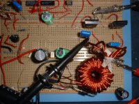
The two usual problems are layout and leakage inductance. Could you post pictures of your transformer and prototype?
No problem. I'm at work at the mo but as soon as i get home i'll take some piccys so you can get a better look. The proto is still on breadboard but it's fed by a high current battery connection direct to the transformer and fet sources.
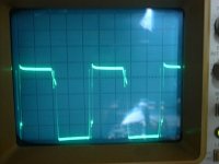
And last but not least no load at all. The controller is now just idleing and somtimes there is no drive at all........
Hope this gives a clue as to why i cant draw more than 100W out of the coil before the voltage drops off????
P.S my scopes trigger was not set very well hence the mirrored pulses. With carefull adjustment the pulses are one high then one low in sequence. I didnt have time as the FET's dont have heatsinks on them and i was juggling with the camera and load connections LOL
Leigh
Attachments
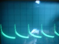
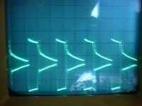
Full Load is when i'm drawing around 100W out of the secondry and the duty runs up to 100% in an attempt to try and supply more power to regulate the output voltage. This was with a 4R load trying to regulate to 50V but on connection of the load the output fell to 22V.
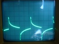
The Half load waveform is with a 47R resistor regulating to 24V on the output.
The Half load waveform is with a 47R resistor regulating to 24V on the output.
Where did you get the core?
It doesn't appear that you're getting any coupling the between primary/secondary windings. With a 4 ohm load on a 1:5 ratio transformer, the voltage on the primary should have been pulled down more, especially with the high Rdson of those FETs.
How much current is it drawing with the 4 ohm load?
Can you post photos of the secondary waveforms with and without the 4 ohm load?
How many primary turns do you have here (5+5 or 15+15)?
When you get the correct transformer, you'll need many more FETs. 6+6 of the IRF3205 should be sufficient.
Hi Perry,
I dont know what core i have as i salvaged it from a mains input choke from a huge power supply. All i can tell you is its 1.5" diameter by 1 inch high. The turns ratio is 10:45
current draw when i fully load the circuit is about 10 amp from the supply. The supply consists of a 17Ah SLA battery in parallel with a 13.8 supply. The secondry waveforms look identical to the primary ones as posted earlier except the amplitude is much larger. The output wavform does not alter under load but its amplitude does drop quite a bit, down as low as 20 volts with the heavy 4R load. As you say its as if there is no coupling between the windings. The windings incidently are made up of 30 strands of 0.4mm for primary and 8 strands of 0.4mm for the secondry.
That core isn't suitable for use as a power transformer.
Try to salvage one that's being used for the power transformer in a car amplifier.
Go to 4+4 on the primary windings.
Insert a fuse (~20 amps) in the B+ line feeding the power supply. When you get the transformer working properly, it's going to try to draw a lot of current (50-70 amps) when you load it with 4 ohms. Your supply and battery may not be up to the task). You won't be able to drive a 4 ohm load with only those two FETs. You'll need at least 4+4 FETs rated at 50 amps or more and they'll have to be on a heatsink. For the final supply, you'll need something like the 6+6 IRF3205s.
I don't know which rectifiers you have but you'll need fast or ultra-fast recovery rectifiers. 4 MUR820s or the equivalent.
Hi,
The diodes i'm using are fast recovery type. MUR360 if i remember. When they start getting hot i'll add more in parallel. Seems the core must be at the root of the trouble then. Is it just material problems and not physical size? What core material/grade should i be looking for? I'm gonna try and dissolve the varnish off and old computer PSU E-core so i can take it apart and re-wind it. That should contain the correct material.
Leigh
Only idle power consumption is related to core material, and it's fine as long as the core can be operated at full duty cycle without drawing a lot of current or causing the MOSFET to heat.
Leakage inductance and coupling are not related at all to core material, they are only related to the shape and placement of the windings. For example, the two primaries should be quite close one to another so that they end up well coupled, it's usually a good idea to split them in several sections in order to be able to pair them closer.
However, at 10A primary current you already need a good PCB and low ESR capacitors in order to achieve low voltage drop on the output. The breadboard layout looks quite bad, both highly resistive and inductive. Note that any parasitic resistance or inductance found at the primary side will appear at the secondary side multiplied by the turn ratio squared, which may cause it to become quite high (a 5:1 ratio results in a 25 factor).
Try making a small PCB, preferably double-sided with continuous ground plane and wide polygon-style tracks for the high current paths, containing input and output filters, the MOSFET, the transformer and maybe a gate driver IC. You can keep the rest in breadboards.
Also, the picture does not show clearly the way in which you wound the transformer, some more information on that would be appreciated. Essentially you should wind the primaries first and pair them as previously mentioned (bifilar, maybe split in smaller sections), then wind the secondaries paired too. Never twist the pairs, just bring them parallel and close. The primaries should be close to the core (for minimum leakage) and secondaries should be close to the primaries too (for best pri-sec coupling), so twisting the wires of each winding in big strands is not a good idea.
Note that you don't really need a big toroid, this is because they require less turns becoming harder to wind and resulting in worse coupling. I prefer small toroids in the 30mm OD range and to use two or more if one is not enough to fit powerful enough windings. Power output capability is not related directly to core size, it's only related to the parasitic inductance and resistance of the windings.
Hi Eva,
So do you think my core is o.k and the fault mst lay with parasitic resistance and inductance?? My windings are wound on the core side by side touching each other in the following form. Primary1,secondry 1, secondry1, primary2,seondry1, secondry1, primary1 ect... Any left over secondrys are on the second layer. In this second prototype coil there is only one secondry as i couldnt fit a second one on and i only need one for testing. The coil is very tight and very full. It doesnt behave any different from the first try which had sloppy turns of 5:25, two secondries and the windings were not spread accross the core evenly. This is why i'm suspecting the core is bad??
I dont know what to believe as everyone seems to have different opinions.
Leigh
- Status
- This old topic is closed. If you want to reopen this topic, contact a moderator using the "Report Post" button.
- Home
- General Interest
- Car Audio
- Switchmode Transformer