Hello all,
I'm doing a refurbish project on a used PPI A404 amplifier. I'm definitely replacing all the e-caps and the transistors (power, diode, output). I may try to freshen the gain pots if I can find new replacements.
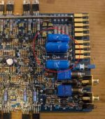
I have a question about the set of 4.7uf capacitors near the inputs. Attached are photos. Are these signal input caps? Or caps on the output stage before the speakers? (they appear to be 100VDC, so I'm not sure) Would there be any improvement in replacing these with something better? (if these are signal input caps, then a nice film cap might do well?)
Any thoughts on other components that would benefit from replacing (same value or different).
Thanks,
Aaron
I'm doing a refurbish project on a used PPI A404 amplifier. I'm definitely replacing all the e-caps and the transistors (power, diode, output). I may try to freshen the gain pots if I can find new replacements.
I have a question about the set of 4.7uf capacitors near the inputs. Attached are photos. Are these signal input caps? Or caps on the output stage before the speakers? (they appear to be 100VDC, so I'm not sure) Would there be any improvement in replacing these with something better? (if these are signal input caps, then a nice film cap might do well?)
Any thoughts on other components that would benefit from replacing (same value or different).
Thanks,
Aaron
Attachments
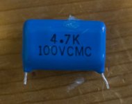
That cap is the input DC blocking cap for each channel there should be one for each channel. Oh and its a Mylar type cap so there is usually no need to consider replacing it unless it tests bad. Its one of the engineered reasons PPI amps sound so good to many people. I have never ever really seen one of these go bad in 25 years of servicing PPI amps....hope this is informative and helpful....")
That's good to know. Thanks. I wondered if they were for input protection because the voltage capacity was so high (100VDC).
Mundorf makes a 4.7uf 250V metallized polypropylene capacitor (M-CAP). Parts Connexion has these for 5.53. Unless there are major objections, I may consider trying them to see if they improve the sound.
Thoughts?
Mundorf makes a 4.7uf 250V metallized polypropylene capacitor (M-CAP). Parts Connexion has these for 5.53. Unless there are major objections, I may consider trying them to see if they improve the sound.
Thoughts?
No objections, its your money to use as you see fit. PPI used this same Mylar cap in all there amps back in the day. It was to soften the sound a bit IMO, and it served them well for many years.
Try Op-amp upgrades in the front end if your really looking for some SQ improvement. And have your channel bias checked with a scope to make sure its set correctly. And adjust your DC offsets to as close to zero as possible. there are adjustment inside for all these set points.
I have found DC offset adjustment to have very satisfying results on SQ improvement, and I usually find it so badly misaligned on the amps that you will find between 20 and 35 milli-volts DC at the speaker terminals with no signal applied. Here again I adjust for less then 1 milli-volts DC offset, and the recheck channel output bias on a scope.
These were pretty OK amps back in the day. Oh also replace ALL the electrolytic caps through out the entire amplifier before you do anything else to the amp. I am sure your are pretty tired by now and the power supply caps alone will make vast improvements on the amps SQ, and stability under load......Best of luck on your project...
I see a pair of pots towards the edges of the board near the output transistors (VR1, VR2, VR5, VR6).
I also see a cluster of 4 pots near the speaker output connections (VR7, VR8, VR9, VR10).
Which ones are DC offset and which ones are bias?
I'm comfortable with doing DC offset adjustments, but I don't have a scope nor the knowledge to do bias adjustments. Will it hurt if I leave the bias untouched?
The ones nearest the outputs are most likely to be the bias pots.
If this amp clamps the transistors with the bottom cover (like most PPI amps), you need to be very careful when operating the amp with the bottom cover removed. The regulators on some of these amplifiers run hot and can fail very quickly if not clamped down. The outputs can also overheat and fail (especially when setting the bias current).
If there are four 2 pin headers in the audio section, install jumpers on them to defeat the biasing. This will help protect the outputs.
After you get the DC offset adjusted, remove the jumpers, reinstall the bottom cover and let the amp idle for a few minutes, then recheck the offset.
When reinstalling the cover screws, install them by hand and make sure that you don't cross thread the screws. They should thread in easily until the head of the screw meets the cover. If you cross thread them, the holes will strip and you won't be able to tighten the cover properly (which will make the amp unusable until the holes were repaired). The sink would be repairable but would require quite a bit of time and effort.
Thanks for the info. I was going to clamp the transistors down to the heatsink by bolting a strip of wood down. This should allow me to apply power to the amp while doing the adjustments.
ok, a couple more questions...
1. Is it okay for me to adjust the DC offset and leave the bias untouched? (RESTATED)
2. I see a couple different options for replacing the power transistors on this forum and at Mouser. To substitute for BDT81/BDT82, I see the 2N6487/2N6490 combo and the 2N6488/2N6491 combo. One has a higher Collector voltage:
Collector-Emitter Voltage:
2N6487/2N6490 - 60 VDC
2N6488/2N6491 - 80 VDC
Collector-Base Voltage:
2N6487/2N6490 - 70 VDC
2N6488/2N6491 - 90 VDC
The original BDT81/82 combo had a rating of 60VDC for both Emitter and Base voltages. However, ON Semi's document indicate that the higher voltage combo are the prefferred devices.
Is it critical to closely match the Collector voltages?
1. yes
2. I'd use the 2N6488/91 made by On-Semi.
You need to use a heavy closed cell foam (weather stripping) between the wood and the transistors. Otherwise, there's virtually no chance to have good pressure on all of the transistors. If you use the bias defeat jumpers, use the clamp to hold pressure on the regulators. It's unlikely that anything else will get hot since you're not going to have a speaker load on the amp.
The preferred devices are more likely to be in stock at more distributors since they can be used in place of the lower voltage devices (with otherwise identical specs).
- Status
- This old topic is closed. If you want to reopen this topic, contact a moderator using the "Report Post" button.
- Home
- General Interest
- Car Audio
- Precision Power PPI A404 refurbish questions