Hello to everybody!!!!!
I'd like to make a Hybrid car Amp.... but I'm not so good in schematics
These are the options I'd like to have:
- Tube preamp
- Final stage with transistors or ICs
- Easy PSU
I think tube preamp and transistors/ICs in final stage is the best solution so you don't need output transformers.
Easy PSU is important for me because I have some trouble in wiring transformer so if the circuit use battery voltage is better.
What about using subminiature tube (for example 6021W) for the preamp?
For the final stage I think using STMicro TDA ICs, but every ideas are welcome.....
Let's try..... and sorry for my awful english!!!!
I've actually successfully done that (built a tube preamp and separate giant solid-state amplifier) but with no interstage processing to remove the tube tonality. ")
I will be posting them soon on DIYAUDIO.com. I'm trying to finish the cooling fan controller for the amplifier this week.
Just as a side note, it sucks, but you may have to "suck it up" and deal with the difficulty of power supply design/troubleshooting for any "real" tube preamp.
Otherwise, the old Planet Audio hybrid amps are still popping up on eBay. I was planning on buying one just to duplicate the PCB & parts list, along with examine the tube layout, but they're still quite popular!! (Had one years ago, wish I kept it!)
Edit: For a starting point (tube preamp and PSU do a search for "Silicon Chip 12AX7 tube preamp" and you'll see what's involved. Their PSU is not so hard to build, but I found an error in the regulation part when I built it. Fixed it and removed the transformer noise. Egad!
Hello to everybody!
Making some "googling" I found this:
PAIA TubeHead
A 12V tube preamp, there is a kit but also the schematic.
But I also found this:
LVPS Power converter
and the schematic
It is a converter from 12V car battery to 170V (in the same site there is also the version for 250V and 300V)
It seems quite easy to build but before using it there are to monitor some points with a scope... that I don't have a scope!!!
If this power supply is ok there is no more the problem of 12V because you can make a "normal" (high voltage) preamp.
For the final stage, with this voltage, you have 2 options:
1. a tube power amp
2. a transistors/ICs power amp (scaling down the voltage).
I prefer the second choice for 3 reasons:
Firstly if you make a tube power amp you also need output trasformers. Secondly, as says benchtester, I think vibration can cause distortion.
Thirdly having an all tubes system is very big and I don't have a "Stretch Limousine"
What do you think?
It depends on the tubes used and the design, etc. But there are several awesome (and really expensive) commercial tube amps & preamps for the car. They have no problems with vibration/microphonics.
I tested my preamp first for microphonic effects over my normal driving route and had no issues.
Jeepix, my suggestion (only a suggestion, there are people a lot more experienced than me here!) is to look at the 12AX7 Silicon Chip design above in my post. It is fairly simple, and my guess is that you could get the SMPS working with no oscilloscope, though not recommended.
Otherwise, if you want to take the easy route, you can do like one guy on DIYAUDIO.com did and get a good 12VDC-120V AC inverter then use a simple linear power supply to power either an amp or preamp.
I'm thinking about doing that for a short time as getting a custom SMPS working can be difficult or time consuming.
Yes, one of the sacrifices you have to make for a custom amplifier, especially a tube amplifier, is the size! But that's engineering-almost everything's a tradeoff.
Can be done, would not recommend the valve part, unless you don't mind changing valves every 3-4 months. But maybe you can get some NOS valves that where used in car radio's, bit hard to find, some of them where made to handle extra vibrations... If it where for Hi-Fi, I'd have recommended 12BH7, Quietest valve I've ever heard in a preamp...
Hello!
thanks MartyM for the advice.
Is it this the preamp? 12AX7 Tube Preamplifier kit
It is quite easy to build... not much components. I will design the PCB this night.
Now before deciding the power supply I must decide what to use as Final Amp.....
I don't know what final amp use: tube, transistor, IC?
Transistor is problaby easy but I have a lot of voltage for the preamp that I have to scale down (I don't know how ) but I think with some regulator and big heatsink. And also big heatsink for the transistor, I think....
IC and what a gainclone? With this I problaby loose all the tube benefits...
Tubes are very beautiful. I already have the right voltage, and for a complete amp I could also made a tube crossover
I'm really in trouble
What I build??? Surely the tube preamp....
Every advice is welcome.... so when I decide for the final stage I also think about the power supply....
Thanks
thanks MartyM for the advice.
Is it this the preamp? 12AX7 Tube Preamplifier kit
It is quite easy to build... not much components. I will design the PCB this night.
Now before deciding the power supply I must decide what to use as Final Amp.....
I don't know what final amp use: tube, transistor, IC?
Transistor is problaby easy but I have a lot of voltage for the preamp that I have to scale down (I don't know how
) but I think with some regulator and big heatsink. And also big heatsink for the transistor, I think....IC and what a gainclone? With this I problaby loose all the tube benefits...
Tubes are very beautiful. I already have the right voltage, and for a complete amp I could also made a tube crossover
I'm really in trouble
What I build??? Surely the tube preamp....
Every advice is welcome.... so when I decide for the final stage I also think about the power supply....
Thanks
Hello! Yes that is the tube preamp I'm referring too.
Well I can tell that perhaps you might consider the National Semiconductor LMxxxx line of Overture power amplifier chips. I used the LM3886 for testing the tube preamp.
Those have design examples that work and they sound nice. I could hear the tonality of the tubes as long as I wasn't using a preamp that did audio processing or etc.
I'm not sure how other amplifier designs or ICs would work with tubes
To have tube sound, you can see some way to do it
http://www.google.com/patents?q=brent+k+butler
http://www.google.com/patents?q=brent+k+butler
Hello!
Very good idea the 12U7. I make a search in google but I don't find preamp with this tube.
Can someone help me?
Using 12V is fantastic because as final stage I decide to make the PA100 - 100W parallel circuit with LM3886 (AN-1192 datasheet). It needs a supply of +30V/-30V.
I think the PSU is quite easy to make (in reality I have no idea how to make it....)
Can someone help me for the preamp and the PSU?
Thanks!!!!!
Hi there, I have posted some relevant information here:
DIY car amplifier info thread/subject
Also, please note that if you are ok with low-power LM3886 amplifier,
it isn't a requirement to use both + & - voltages- you can use only a + voltage, at least for testing if you like (there are design examples for single-supply amplifiers).
Has anyone used the 12U7 and can vouch for it as a viable preamp tube? I bought two and never used them!! (Foo on me!)

MartyM said:Hi there, I have posted some relevant information here:
DIY car amplifier info thread/subject
Also, please note that if you are ok with low-power LM3886 amplifier,
it isn't a requirement to use both + & - voltages- you can use only a + voltage, at least for testing if you like (there are design examples for single-supply amplifiers).
Has anyone used the 12U7 and can vouch for it as a viable preamp tube? I bought two and never used them!! (Foo on me!)
Yes, I've done some experimentation with a 12U7 preamp. Very viable. It may help some to think of the tube as a normal 12AU7 optimized to run on a 12-24V B+, because that's exactly what it is! If you have two of them sitting side by side, made by the same manufacturer, you cannot tell them apart visually, other than the "A" being missing!
Notice in the later versions of the Sopht amp, they did away with the cathode caps and resistors on the 12U7. Anyone wishing to try this, I suggest you start from that point as well, as my next step was doing away with them also.
Don Taylor
BrassTeacher
EDIT: If you want to try this, and can't find a 12U7, try it with a regular 12AU7 anyway. I'm told it works, it's just that the 12U7 is more attuned to the lower voltages.
Hello to everybody
I'm full of work for some days so I can't watch the forum... sorry!
I try to go ahead and I decide:
1. make a tube buffer with ECC88 (or 6922, 6DJ8, 6N1P... all compatible)
2. for the final amp go with a "normal" LM3886 GC
So I find out the "clone" schematic of Tube Buffer X10D and the normal application present in the datasheet of National about LM3886.
I try to put everything in Eagle and this is what come out....
The schematic:
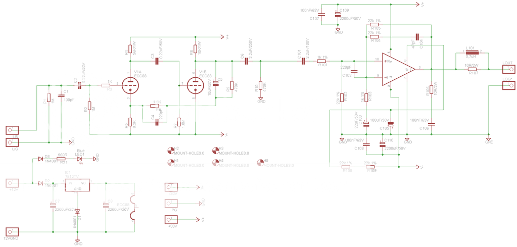
and the PCB:
The power supply is +/-30V for the tubes, LM3886 and 12V for the filaments and led (I also put one blue led to insert under the tube socket)
The schematic and PCB are about half ch (L or R) so you need two to have a complete ch - in my case i will have to build 4 (FL, RL, FR, RR)
I'm not very good with Eagle so I think the PCB is quite awful and I'm very concerned about the noise and the 12V entrance (I think it is too much near the output of amplifier).
Please double check the schematic and PCB (I DON'T MAKE TEST) and give me some advice to make it better (if you need I can send .sch and .pcb files).
After this I must start to think to SMPS It's the worst part of the work...
So please check the schematic and PCB, give me some comments and advices... and also some advice about SMPS.
Thanks!!!!
Andrea
I'm full of work for some days so I can't watch the forum... sorry!
I try to go ahead and I decide:
1. make a tube buffer with ECC88 (or 6922, 6DJ8, 6N1P... all compatible)
2. for the final amp go with a "normal" LM3886 GC
So I find out the "clone" schematic of Tube Buffer X10D and the normal application present in the datasheet of National about LM3886.
I try to put everything in Eagle and this is what come out....
The schematic:
and the PCB:
The power supply is +/-30V for the tubes, LM3886 and 12V for the filaments and led (I also put one blue led to insert under the tube socket)
The schematic and PCB are about half ch (L or R) so you need two to have a complete ch - in my case i will have to build 4 (FL, RL, FR, RR)
I'm not very good with Eagle so I think the PCB is quite awful and I'm very concerned about the noise and the 12V entrance (I think it is too much near the output of amplifier).
Please double check the schematic and PCB (I DON'T MAKE TEST) and give me some advice to make it better (if you need I can send .sch and .pcb files).
After this I must start to think to SMPS
It's the worst part of the work... So please check the schematic and PCB, give me some comments and advices... and also some advice about SMPS.
Thanks!!!!
Andrea
Hi Andrea, nice post. I will have to have some time to look over your schematic and PCB layout.
Please do not be too worried about your PCB layout skills-it takes time, plus EAGLE is awkward in some regards (that is why I do not use it for my work-related designs but it's ok for hobby/DIY work).
I do have some things, from my hard-learned experience that I hope will be helpful to you!
Start with most "important" or most frustrating!
1. Design will need to incorporate provision(s) for dealing with ground loop noise, by noise-cancelling circuit, isolated SMPS grounds, and/or ground loop isolator transformers on the audio inputs
2. It can be very helpful to provide jumpers or headers in the design to:
-Provide easy access to remote on, +12V, gnd, and +/-30V for add-on circuitry such as mute circuits, bridging circuits, preamps, etc.
-Provide a way to connect and disconnect power and signal grounds for aid in troubleshooting noise (like by using a 2-pin .1" header and jumper)
3. Make sure you use shielded audio cables when you build the unit, so you can reduce induced noise (this worked greatly on my 8-channel LM3886 car amp!)
4. If you can do it, leave exposed copper (no solder mask) in areas where you may need to modify the PCB when debugging it. That way you will not have to scratch off the solder mask like I did.
5. Make sure the diameter of all mounting holes in the PCB is plenty for the components!!
6. Always use standard and commonly available or low-cost connectors & pins where possible.
Basically try to think of the little things you can do now to help you when you have to actually debug the real hardware.
But most importantly, since it is feasible to do so, I would not produce a PCB until having a working proof-of-concept prototype. Building the LM3886 amplifier by hand is very easy to do and test, and the SMPS can be done by hand also without terrible pain!!
Just some ideas to consider. Hearing your amplifier (and tube preamp) working for the first time is wonderful. Dealing with ground loop noise, however, is not!!!
Please do not be too worried about your PCB layout skills-it takes time, plus EAGLE is awkward in some regards (that is why I do not use it for my work-related designs but it's ok for hobby/DIY work).
I do have some things, from my hard-learned experience that I hope will be helpful to you!
Start with most "important" or most frustrating!
1. Design will need to incorporate provision(s) for dealing with ground loop noise, by noise-cancelling circuit, isolated SMPS grounds, and/or ground loop isolator transformers on the audio inputs
2. It can be very helpful to provide jumpers or headers in the design to:
-Provide easy access to remote on, +12V, gnd, and +/-30V for add-on circuitry such as mute circuits, bridging circuits, preamps, etc.
-Provide a way to connect and disconnect power and signal grounds for aid in troubleshooting noise (like by using a 2-pin .1" header and jumper)
3. Make sure you use shielded audio cables when you build the unit, so you can reduce induced noise (this worked greatly on my 8-channel LM3886 car amp!)
4. If you can do it, leave exposed copper (no solder mask) in areas where you may need to modify the PCB when debugging it. That way you will not have to scratch off the solder mask like I did.
5. Make sure the diameter of all mounting holes in the PCB is plenty for the components!!
6. Always use standard and commonly available or low-cost connectors & pins where possible.
Basically try to think of the little things you can do now to help you when you have to actually debug the real hardware.
But most importantly, since it is feasible to do so, I would not produce a PCB until having a working proof-of-concept prototype. Building the LM3886 amplifier by hand is very easy to do and test, and the SMPS can be done by hand also without terrible pain!!
Just some ideas to consider.
Hearing your amplifier (and tube preamp) working for the first time is wonderful. Dealing with ground loop noise, however, is not!!!Hello to everybody,
I found this site Coldamp that have a SMPS module.
I know it isn't DIY but I'm a little in trouble making the SMPS so if I find already done is better (for me )
But I have some questions:
1. the minimun output voltage is +/-38V do you think it's suitable for my project? The tubes require 30V and 38V for LM3886 is quite the limit...
2. the tubes filaments need 15V but on the board I've only 12V....
3. as final amp I've got for small boards (front L, front R, rear L and read R) each one with one LM3886 so I have 4 +VCC and 4 -VCC but as output of the SMPS I've 2 +VCC and 2 -VCC... may I use and Y cable to split the voltage?
Thanks for the answers.....
Andrea
I found this site Coldamp that have a SMPS module.
I know it isn't DIY but I'm a little in trouble making the SMPS so if I find already done is better (for me
)But I have some questions:
1. the minimun output voltage is +/-38V do you think it's suitable for my project? The tubes require 30V and 38V for LM3886 is quite the limit...
2. the tubes filaments need 15V but on the board I've only 12V....
3. as final amp I've got for small boards (front L, front R, rear L and read R) each one with one LM3886 so I have 4 +VCC and 4 -VCC but as output of the SMPS I've 2 +VCC and 2 -VCC... may I use and Y cable to split the voltage?
Thanks for the answers.....
Andrea
- Status
- This old topic is closed. If you want to reopen this topic, contact a moderator using the "Report Post" button.
- Home
- General Interest
- Car Audio
- Hybrid Car Amp... let's try