i work at the car audio store and we had a memphis amp laying around and i was about to toss it in the trash since it was out of warranty but then i thought... it would be a good project
so to see whats happening i hoked it up to 12v power supply converter that we have in the shop and heres what happened.
the amp turned on( green light) no protection/overcurrent/dc offset/thermal lights came on
but the headunit that was hooked up to the supply shut off and i heard buzzing sound thrun speakers so that means theres a short in it somehwere?
at home i unscrewed it and start popping off the transistors and 4 of them fell off their legs once i unglued them i wiggled rest of them and they seem to be on there ok.
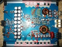
heres the images of the top/bottom and transistors
so to see whats happening i hoked it up to 12v power supply converter that we have in the shop and heres what happened.
the amp turned on( green light) no protection/overcurrent/dc offset/thermal lights came on
but the headunit that was hooked up to the supply shut off and i heard buzzing sound thrun speakers so that means theres a short in it somehwere?
at home i unscrewed it and start popping off the transistors and 4 of them fell off their legs once i unglued them i wiggled rest of them and they seem to be on there ok.
heres the images of the top/bottom and transistors
An externally hosted image should be here but it was not working when we last tested it.
An externally hosted image should be here but it was not working when we last tested it.
An externally hosted image should be here but it was not working when we last tested it.
An externally hosted image should be here but it was not working when we last tested it.
An externally hosted image should be here but it was not working when we last tested it.
An externally hosted image should be here but it was not working when we last tested it.
An externally hosted image should be here but it was not working when we last tested it.
That looks weird. I've never seen that myself in a car amp. 
However I can imagine that this is due to mechanical stress - in particular vibrating of the PCB - since there is no additional screw that might hold the PCB in the middle, i.e. on the little PCB tongue between the transistor triplets on each side of the heatsink. I would recommend to drill additional holes in there to screw the PCB to the heatsink.
I can only guess that this amp might be installed flat/horizontally in a car and each dip the previous owner was driving through let the PCB bend and mechanically oscillate. This for sure will eventually tend to cracks in the PCB (pads, tracks, ...) or destroy the component leads, as can be seen in this case.
Anyhow it's a shame that the whole (large and heavy) PCB has only four screws to hold it in the heatsink-case. The electronics (schematic, component selection, etc.) might be OK but the mechanical stuff is not really designed for automotive use IMHO.
One of the basic electronic rules is not to stress electronic components with mechanical stress and in particular solder joints and terminal leads, etc.
I can see very clearly from the pictures that the choke is glued to the PCB plus a single cable strap (I guess because of lack of connection leads soldered to the PCB) but the transformer choke doesn't appear to be glued/strapped/screwed to the PCB at all - just soldered I guess!?!
Well, replace all broken parts and get that PCB tight and stiff with added screw-points into that heatsink-case and I'm sure you'll have fun with that amp for many many more years.")
However I can imagine that this is due to mechanical stress - in particular vibrating of the PCB - since there is no additional screw that might hold the PCB in the middle, i.e. on the little PCB tongue between the transistor triplets on each side of the heatsink. I would recommend to drill additional holes in there to screw the PCB to the heatsink.
I can only guess that this amp might be installed flat/horizontally in a car and each dip the previous owner was driving through let the PCB bend and mechanically oscillate. This for sure will eventually tend to cracks in the PCB (pads, tracks, ...) or destroy the component leads, as can be seen in this case.
Anyhow it's a shame that the whole (large and heavy) PCB has only four screws to hold it in the heatsink-case. The electronics (schematic, component selection, etc.) might be OK but the mechanical stuff is not really designed for automotive use IMHO.
One of the basic electronic rules is not to stress electronic components with mechanical stress and in particular solder joints and terminal leads, etc.
I can see very clearly from the pictures that the choke is glued to the PCB plus a single cable strap (I guess because of lack of connection leads soldered to the PCB) but the transformer choke doesn't appear to be glued/strapped/screwed to the PCB at all - just soldered I guess!?!
Well, replace all broken parts and get that PCB tight and stiff with added screw-points into that heatsink-case and I'm sure you'll have fun with that amp for many many more years.
Yeah, poor board design. They should have put several screw points in the areas the transistors were bolted for the pcb. The design probably allowed the pcb to resonate at a certain frequency (most likely a low bass note) and crack the transistors loose. Easy fix for you as long as nothing else went bad as a result.
I have seen the same issue with Hifonics Brutus amps. I add rubber supports under the main board to stop the board from vibrating as much as possible. Yes its bad design.
This amp looks to be a Sony look alike inside . It has the same guts and design as the Sony Explod 1600 Class D pentagon shaped amps inside. I mean part for part its a Sony D amp.
Those SSP45n20A's will almost impossible to find. I think I have 10 or 12 pieces left in my stock, but there is no new stock for those. I think Perry used IRF3415 to replace them but you might have to recalculate the gate resistor value to get that to work.
Good luck on your project...
i belive that this is like 4th amp that we had to replace of the same model and we kept sending them for warranty but somehow this one was out of luck i think i found some online yesterday.
say they are burned out...
what other components should i check before powering it up?
say they are burned out...
what other components should i check before powering it up?
besides what others have already suggested...
you could also try drilling holes on the PCB "tabs" between the fets (see red arrows in attached picture) and on the heatsink underneath those and using self tapping screws to fasten PCB to heatsink to help lessen PCB flexing.
you could also try drilling holes on the PCB "tabs" between the fets (see red arrows in attached picture) and on the heatsink underneath those and using self tapping screws to fasten PCB to heatsink to help lessen PCB flexing.
Attachments
thanks quan that makes sense donno why they didnt use it for screws in the first place
but say itsa mechanical failure only( transistor legs broken) what other parts could this damage.( i should check for)
and if i was to substitute those with different transistors is there a page refference i can look them up at?
but say itsa mechanical failure only( transistor legs broken) what other parts could this damage.( i should check for)
and if i was to substitute those with different transistors is there a page refference i can look them up at?
The class D section of this amp is virtually identical to the Sony XM-D400P5 (down to the circuit board designations).
The SSP45N20A transistors are available from a distributor but they wouldn't work in any of the amps I installed them in (including one of these amps).
The IRF3415s are often a drop-in replacement. I've used hundreds of them on MTX amps like the 6500D. They have a relatively low voltage rating so they can't be used in the larger MTX and Sony amps (XM-D1000P5). They were not a drop-in replacement in the PR1KD I used them in. Several resistor values had to be changed to get the amp to operate properly.
There are many amps that don't provide adequate support for the heavy components and the circuit boards. On most of the class D amps I work on, I add supports like the ones shown in the images below. This is 3/8" ABS stock cut to fit the amp. The upper and lower supports trap the board between the bottom cover and the heatsink.
http://www.bcae1.com/temp/IMG_7596b.jpg
http://www.bcae1.com/temp/IMG_5861b.jpg
Sorry to confuse you.
In some class D amplifiers, the only transistors that work properly are the ones that were available when the amp was produced. If the manufacturer changes the transistor in any way, the transistor won't work in the amplifier (without modifying the drive circuit of the amp). The transistor may have essentially the same specifications but they still won't work properly. The old MTX, Xtant and Sony amps (all of which use a VERY similar self oscillating circuit) are the worst.
If you can find some of the original transistors (new old stock), the amp will likely be easily repaired. If the transistors are, in any way, different from the originals (even though they are precisely the same part number), they may not work.
If you find replacements and the amp draws excessive current, trips the overcurrent protection circuit, runs hot or produces distorted output, there's a good possibility that the replacements are not compatible.
I am glad that I found this post because my Memphis 16-PR1.5KD stopped working yesterday too. It powers up, but emits a high pitch whine through the subwoofer. I guess the transistors popped off of mine, so I am going to pull it and see.
At least one of my friends is an electronics geek and has a soldering station.... I just hope this is an easy fix.
At least one of my friends is an electronics geek and has a soldering station.... I just hope this is an easy fix.
hi i'm new to the site and i'm fixing the same amp. so whats the best thing to do? try getting new old parts or upgrading to the new P/N? i figure upgrading would be the best because any future repairs would be easier to replace the parts, so what do i need to do to do the upgrade?
In the last few I've repaired, I used IRF3415s.
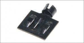
There is a row of 8 driver transistors near the outputs. I'd recommend replacing all 8 of those. Use MPSW42s in place of the MPSA42s. You should also add clip-on heatsinks (attached image) to the W42s.
Check the two resistors marked 471 (R114, R115). They often open.
Many of the SMD transistors will have bad solder connections. You should desolder them with braid and resolder their connections.
Check transistors Q118, 119, 120, 121 and 122 out of the board. Check on both diode check and on ohms to determine if any have any reverse leakage. If you don't know how to check them, let us know.
These amps have a lot of bad solder connections. Many times it's difficult to remove enough of the old solder to produce a reliable connection. If there are transistors with solder connections that need to be repaired, you should remove the transistor, add additional, new solder and desolder from both sides of of the board. Liquid or paste solder flux can make the work on these amps a bit easier.
When desoldering, never allow the tip of the soldering iron to touch the solder pads (most are already damaged and are easily lifted). Apply enough solder so you can heat the solder on the pad without touching the pad. A desoldering pump will be less likely than desoldering braid to cause damage.
If there is any question as to the condition of the via (copper feedthrough) in the board, solder both top and bottom when reinstalling the transistors.
To help keep the board from being further damaged from heat, you should install the transistor so their body is well off of the board. If the board shows signs of heat damage, the transistor likely runs hot under normal operating condition and should have a clip on heatsink.
Attachments
Try replacing the driver transistors and any transistors that are leaking or are otherwise defective. Resolder all of the resistors and transistors that need it. Replace any defective resistors. If it fails to oscillate, then you may have to try changing the values of some of the resistors.
- Status
- This old topic is closed. If you want to reopen this topic, contact a moderator using the "Report Post" button.
- Home
- General Interest
- Car Audio
- Memphis 16-PR1KD amp repair help (pix)