I am still in the planning stage for a DIY car amplifier and was hoping those that have already built car amps will provide some clarification.
I plan to base my DIY amp on the National chips. Most likely the LM3886, LM4780 or the LME49810... The LME49810 really got my attention because of its capabilities...
Question #1-
Most car amps have gain controls... Where should a pontmeter be placed in the signal chain to serve as gain ?
Question #2-
Does anyone have a good SMPS design for a 500 watt amplifier section ?
Question #3-
Please give me some good experienced advise on building a DIY amplifier.
PS
I would also like to build a multiband equilizer for automotive use... any links or advise ?
Thanks !
J
Hi J-you came to exactly the right place.
I set out for a very ambitious project-I designed and built my own 8-channel high power car amplifier. I have an Alpine DSP processor with real 5.1 surround outputs and wanted to finally have an amplifier that supports all of them, not just some, along with 2 spare channels.
1/2 of the object of this adventure was to gain the (heavy) experience from this for both audio and power supply design and use from doing what the average person can't fathom-building your own car amp!
The other 1/2 was to have the first great-sounding car amp with a direct audio path and yet no ground loop noise. My tube preamp is not very fun if a bunch of processing removes the tonality.
So let me address your issues:
Question #1-
-You might consider having the gain be constant like in the data sheet and use the volume input as shown in the design examples. I realize car use is different from home use, but I really wish I had mounted my input level controls together on an easily accessable PCB near the front.
Question #2-
My SMPS units I tested only to 300W or so, but I use multiple power supplies (3)-dedicated for the groups of channels and one for the subwoofer. You can follow the Project 89example at http://sound.westhost.com/project89.htm if you are a beginner. It works well for building your own amp, but once you get more experience you'll see where it could use changes.
One reason is that when I designed/bought my PCBs I got 5 whether I wanted that many or not, so I put them to good use. Also modified one spare one for +260V for a car tube preamp.
Question #3-
Here's a lot of advice about building your own car amp:
-Figure out your requirements for input signal voltages, speaker impedances to be used, and how much power you think you need
realistically.
-Get prototypes working for both the audio amp sections and the SMPS. It's not a bad as it may seem!!
-Test them all together and [this is critical!] test them all in the car in real-world conditions before finalizing your design. Don't forget to test with the engine running as noise can be introduced and the SMPS supply voltage will change too.
-You will find noise somewhere! Prepare to spend some time and effort eliminating it. That can be really easy, or hard if you have strict requirements.
-I wish I had used a slightly better SMPS chip like the TL494, but the SG3525 is ok for basic stuff. Just that there are better alternatives...
-It's helpful if you allow yourself room on the PCBs to make mods & upgrades
Also:
1. Ground loop noise is a reality for car installations. You need to ensure proper ground techniques in both your amp/power designs as discussed on DIYAUDIO.com (search gives good results)
2. Don't have to make your PCBs so tiny-it makes them harder to work on.
3. I would recommend standard & readily available parts and connectors when possible. My first speaker & power terminals on the amps were screw terminals, and were a pain. I hardwired Molex wire-to-wire connectors (.062" & .093" pins) and am happier now.
I made my own high-current DC-in terminals using 4-gauge car stereo brass/gold plated terminals.
4. Heatsinks and cooling are super important. The design examples for the PA100 get really hot under use even using the recommended size. Condsider adding a small fan.
5. Had to add a power-on mute circuit as the subwoofer BPA200 created noise when the SMPS powers up. Again, had to keep power isolated or ground loop noise path was created.
6. Got lots of my parts, amp chips, custom metal work, & heatsinks from eBay sellers.
7. Common hardware from Lowe's & Home depot is extremely helpful: hot glue, machine screws & nuts, plastic (isolated) nuts, black screws, flat & L-brackets, Lexar or acrylic sheets.
A final hurdle was eliminating ground loop noise without sacrificing audio. There are two ways:
1. Isolate ground or filter noise in the audio path (easier)
2. Isolate the ground in the power path (source of noise)
Cheap ground loop isolators are commonly used in car stereo but can affect audio response and are a "patch" not a cure. I installed a lot of systems before graduating college. There are better ones (Jensen) but they're expensive. Also balanced circuits can be used but that's more circuitry and time but another option.
I used isolated SMPS grounds and trial-and-error to find the best connectivity (connected all SMPS outputs together, still isolated from chassis ground) and a star topology. Then I made an isolated DC-DC power module for the DC power of my DSP (audio source). That eliminated the source of the noise, and did not require a compromise in my audio.
Keep your head up, it's a tough but rewarding project.
My amp surprised me in it's sound (LM3886's 7 x PA100, 1 x BPA200) and is better than my original Planet Audio amps!
EQ: Not real sure about "real" equalizer designs out there, I always used a decent processor or AudioControl aftermarket units.
There used to be some EQ ICs that could be daisy-channed but I think they're obsolete now.
Don't forget your SMPS can provide the +/- voltages to power a nice homebuilt EQ, crossover, or etc!
-------------------------------------------------------------------------------------
Note: I owe a lot of thanks to the guys at DIYAUDIO.com who were nice & helped me!
Note#2: If you find people who claim you can't do it, don't be discouraged. If you're smart enough to be at the DIYAUDIO.com, you're smart enough to build your dream project. Those who can't, talk. Those who can, do!")
I set out for a very ambitious project-I designed and built my own 8-channel high power car amplifier. I have an Alpine DSP processor with real 5.1 surround outputs and wanted to finally have an amplifier that supports all of them, not just some, along with 2 spare channels.
1/2 of the object of this adventure was to gain the (heavy) experience from this for both audio and power supply design and use from doing what the average person can't fathom-building your own car amp!
The other 1/2 was to have the first great-sounding car amp with a direct audio path and yet no ground loop noise. My tube preamp is not very fun if a bunch of processing removes the tonality.
So let me address your issues:
Question #1-
-You might consider having the gain be constant like in the data sheet and use the volume input as shown in the design examples. I realize car use is different from home use, but I really wish I had mounted my input level controls together on an easily accessable PCB near the front.
Question #2-
My SMPS units I tested only to 300W or so, but I use multiple power supplies (3)-dedicated for the groups of channels and one for the subwoofer. You can follow the Project 89example at http://sound.westhost.com/project89.htm if you are a beginner. It works well for building your own amp, but once you get more experience you'll see where it could use changes.
One reason is that when I designed/bought my PCBs I got 5 whether I wanted that many or not, so I put them to good use. Also modified one spare one for +260V for a car tube preamp.
Question #3-
Here's a lot of advice about building your own car amp:
-Figure out your requirements for input signal voltages, speaker impedances to be used, and how much power you think you need
realistically.
-Get prototypes working for both the audio amp sections and the SMPS. It's not a bad as it may seem!!
-Test them all together and [this is critical!] test them all in the car in real-world conditions before finalizing your design. Don't forget to test with the engine running as noise can be introduced and the SMPS supply voltage will change too.
-You will find noise somewhere! Prepare to spend some time and effort eliminating it. That can be really easy, or hard if you have strict requirements.
-I wish I had used a slightly better SMPS chip like the TL494, but the SG3525 is ok for basic stuff. Just that there are better alternatives...
-It's helpful if you allow yourself room on the PCBs to make mods & upgrades
Also:
1. Ground loop noise is a reality for car installations. You need to ensure proper ground techniques in both your amp/power designs as discussed on DIYAUDIO.com (search gives good results)
2. Don't have to make your PCBs so tiny-it makes them harder to work on.
3. I would recommend standard & readily available parts and connectors when possible. My first speaker & power terminals on the amps were screw terminals, and were a pain. I hardwired Molex wire-to-wire connectors (.062" & .093" pins) and am happier now.
I made my own high-current DC-in terminals using 4-gauge car stereo brass/gold plated terminals.
4. Heatsinks and cooling are super important. The design examples for the PA100 get really hot under use even using the recommended size. Condsider adding a small fan.
5. Had to add a power-on mute circuit as the subwoofer BPA200 created noise when the SMPS powers up. Again, had to keep power isolated or ground loop noise path was created.
6. Got lots of my parts, amp chips, custom metal work, & heatsinks from eBay sellers.
7. Common hardware from Lowe's & Home depot is extremely helpful: hot glue, machine screws & nuts, plastic (isolated) nuts, black screws, flat & L-brackets, Lexar or acrylic sheets.
A final hurdle was eliminating ground loop noise without sacrificing audio. There are two ways:
1. Isolate ground or filter noise in the audio path (easier)
2. Isolate the ground in the power path (source of noise)
Cheap ground loop isolators are commonly used in car stereo but can affect audio response and are a "patch" not a cure. I installed a lot of systems before graduating college. There are better ones (Jensen) but they're expensive. Also balanced circuits can be used but that's more circuitry and time but another option.
I used isolated SMPS grounds and trial-and-error to find the best connectivity (connected all SMPS outputs together, still isolated from chassis ground) and a star topology. Then I made an isolated DC-DC power module for the DC power of my DSP (audio source). That eliminated the source of the noise, and did not require a compromise in my audio.
Keep your head up, it's a tough but rewarding project.
My amp surprised me in it's sound (LM3886's 7 x PA100, 1 x BPA200) and is better than my original Planet Audio amps!
EQ: Not real sure about "real" equalizer designs out there, I always used a decent processor or AudioControl aftermarket units.
There used to be some EQ ICs that could be daisy-channed but I think they're obsolete now.
Don't forget your SMPS can provide the +/- voltages to power a nice homebuilt EQ, crossover, or etc!
-------------------------------------------------------------------------------------
Note: I owe a lot of thanks to the guys at DIYAUDIO.com who were nice & helped me!
Note#2: If you find people who claim you can't do it, don't be discouraged. If you're smart enough to be at the DIYAUDIO.com, you're smart enough to build your dream project. Those who can't, talk. Those who can, do!
Hi, I recently had malware to ruin my home PC, and the restoration process wiped out all my design files, but I still have notes and some paper documents that are very important, like turns ratios, magnet wire used, and so on (transformers).
The schematics for the LM3886-based amps I made are pretty much identical to the PA100 & BPA200 design examples from National.
The SMPS of mine was a slightly modified version of the Project 89 I mentioned above. The rest is related to the power-on subw. mute timer, LED boards (that super easy), and my BPA200 balanced driver circuit with variable gain (that's really easy too).
If you need some perhaps I can scan & post them. I guess I need to anyway...since my other files are gone, but the test data on paper was pretty essential anyway.
Either way I'm sure I can answer your questions. Information on the web has been pretty poor and getting everything working was pretty interesting.
Attachments
Ok, if you could give me a small amount of time I'll scan and post them here to help you and others. I still have a lot of useful stuff like where I got my transformer cores (toroidal), wire, and misc.
The PCBs are not a challenge in my opinion, if you start with a decent design, so that should not be a real hurdle for anyone comfortable making/working with a PCB and assembly.
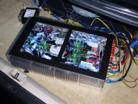
Note: haven't received fans yet so they're not shown on the amp photo yet. Still have to figure out how to mount them.
The PCBs are not a challenge in my opinion, if you start with a decent design, so that should not be a real hurdle for anyone comfortable making/working with a PCB and assembly.
Note: haven't received fans yet so they're not shown on the amp photo yet. Still have to figure out how to mount them.
Attachments
MartyM:
You really did a great job on your amplifier... Looks wonderful !
I plan to design mine similar to the old school Adcom car amps. I want to put the heatsink in the center of the amplifier with the amplifier section on one side and the power supply section on the other. The heatsink should provide a means to seperate the two sections. I also plan to use fans on the heatsink to help with cooling.
Also, if I am understanding the DIY amplifier process correctly... I can build say the PA100 amplifier section for my car just as I would for a home build... The difference is in the SMPS used to link the amplifier section to the cars electrical system. Correct ?
J
Hi, yes that is pretty much the difference along with these factors:
1. Speaker impedance: The PA100 can support < 4 Ohms
2. Power: I made sure I had at least much power as my originals or I knew I wouldn't be happy because it would be like downgrading (The PA100s can exceed my old amp's rating)
3. Ground loop noise: Can be a real nightmare in a car! So you will have to try to decide how to approach noise elimination and make provisions in your designs, including the SMPs & amps
I think those are the fundamental differences-the rest was minor stuff related the construction, amp bridging, performance, etc.
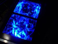
Thanks for the comments...you should have seen me, outside in the trunk at least 15-20 times, doing "real world" testing...my neighbors seeing a glowing blue project. And one time flames came out of a MOSFET when I caused a fault!
I almost considered "throwing in the towel" because of the noise issue because I was frustrated and had my heart on solving the challenge the way I wanted it (nothing in signal path); but I decide to push on and finally solved it.
I think I will be able to help you and others by not repeating some of the initial errors or oversight I made!
Also, Perry Babin is a poster on this board, and is very knowledgeable about car amps/repair/noise and his comments were helpful and very accurate.
1. Speaker impedance: The PA100 can support < 4 Ohms
2. Power: I made sure I had at least much power as my originals or I knew I wouldn't be happy because it would be like downgrading (The PA100s can exceed my old amp's rating)
3. Ground loop noise: Can be a real nightmare in a car! So you will have to try to decide how to approach noise elimination and make provisions in your designs, including the SMPs & amps
I think those are the fundamental differences-the rest was minor stuff related the construction, amp bridging, performance, etc.
Thanks for the comments...you should have seen me, outside in the trunk at least 15-20 times, doing "real world" testing...my neighbors seeing a glowing blue project. And one time flames came out of a MOSFET when I caused a fault!
I almost considered "throwing in the towel" because of the noise issue because I was frustrated and had my heart on solving the challenge the way I wanted it (nothing in signal path); but I decide to push on and finally solved it.
I think I will be able to help you and others by not repeating some of the initial errors or oversight I made!
Also, Perry Babin is a poster on this board, and is very knowledgeable about car amps/repair/noise and his comments were helpful and very accurate.
If you're going to drive the amplifiers from different sources (i.e. sub from the head unit and others from a second signal processor), you may want to use multiple, isolated power supplies or an active noise cancelling circuit on the input of each amp. Either will reduce headaches trying to chase down ground loops.
When you build the supply, use a core that's designed for power transformers. Too many have tried and failed because they had the wrong core. The F-material cores from CWSbytemark are a good choice. For 500 watts, the F-193A-F core will be a good choice. If you're going to use multiple supplies, you can use the smaller 1.5" diameter F-material cores.
http://www.cwsbytemark.com/index.php?main_page=index&cPath=206_221
I'm not familiar with the ICs you're using but if you are going to get full power from them and each one has a different maximum operating voltage, you will need to use multiple regulated power supplies.
Hi, I have three files (.zip format) that give info. Unfortunately it won't let me attach the .zip file so I'll be happy to send them to anyone who emails me. Sorry...the limit here is too small!
Here are the notes I scanned...they are notes regarding:
-Parts source for 1.54" toroid, and wire, based on using my Planet Audio commercial amps as design examples
-Turns ratio and number-of-conductors data for both primary transformer turns (Np) and secondary (Ns)
-Actual measured output voltages for a given input voltages, tested in real car environment
Also:
-Bridging op amp schematic w/ adjustable gain for the subwoofer channel bridging module (but of course will work for full-range channels if you want to have channels that can be both bridgeable or stereo useable)
Basically, the good part is that the schematics in Project 89 are pretty good, and I had to make a few improvements, but it will work if built correctly, first time!
You will need to get a prototype SMPS running and test it on a load...the voltage output will not be correct without a load test.
Addittionally, you may find it helpful to get scrap parts from dead PC (ATX) power supplies. I got resistors, capacitors, and heatsinks for my SMPS MOSFETs from some. Also a fan or two.
This is a good starting point, I think.
I do have a pic attached of the first test of one of the amp modules, but with an undersized heatsink.
Attachments
Check this thread:
http://www.diyaudio.com/forums/showthread.php?s=&threadid=111566
It's a complete full-range class-D car amplifier.
http://www.diyaudio.com/forums/showthread.php?s=&threadid=111566
It's a complete full-range class-D car amplifier.
- Status
- This old topic is closed. If you want to reopen this topic, contact a moderator using the "Report Post" button.
- Home
- General Interest
- Car Audio
- Amplifier design questions