Hi, I’m new to the forum but have been reading the posts here for a few months.
I’ve repaired a few old school class AB amps in the past but this is my first class D amp. I bought this amp in non-working condition to try to repair for a project and I’m not sure where to start. As the title states it a kenwood KAC-9102D, it does not power up at all. I checked the power and output transistors on the board and they seem to be ok. I did a search on here and found this thread:
9102D thread
I took some power readings for Q3 and the tl4941 IC. I used a pc power supply for bench testing, it outputs 10.68 Volts at 10 amps(I’ve used this same power supply to test class AB amps that I have repaired). Here are the results I got:
TL4941 – pin1 .03, pin2 0, pin3 0, pin4 .03, pin5 .04, pin6 0, pin7 0, pin8 1.38, pin9 .325, pin10 .325, pin11 1.36, pin12 1.36, pin13 .64, pin14 .64, pin15 .64, pin16 0
Q3 – E=10.64, C=1.36, B=10.14
The few amps I have repaired have only had shorted transistors so I’m not sure where to go from here. The tools I have at my disposal are a DMM, an analog multi meter, and an oscilloscope. I understand the concepts behind how amps function and have built simple audio circuits before but I’m really kind of a newbie at this so any help would be greatly appreciated.
If the voltage from collector to emitter of Q2 is less than 1v, Q3 is defective. If you short from the collector to the emitter of Q3, the amp should power up. This will allow further testing.
If you short between those pins on Q3, have the transistors clamped to the heatsink and have a 10 amp fuse in the B+ line.
If you short between those pins on Q3, have the transistors clamped to the heatsink and have a 10 amp fuse in the B+ line.
Perry Babin said:If the voltage from collector to emitter of Q2 is less than 1v, Q3 is defective. If you short from the collector to the emitter of Q3, the amp should power up. This will allow further testing.
If you short between those pins on Q3, have the transistors clamped to the heatsink and have a 10 amp fuse in the B+ line.
just to clarify, do you mean put the positive probe on Q2 collector and negative probe on Q2 emitter and read the voltage or read the voltage from the collector referenced from ground and then from the emitter refrenced from ground and subtract?
I had one that Q3 was bad, B & C had 1.7v powered up and 1.3 no remote and E was always B+ supply. Another one I had blew the ground trace on the board and thus took power away from the input section, but still had power to PS, it was hard to see so check the ground areas on the board. I think the case grounded and did it but not sure so look at case ground to board on bottom cover screw, mine was melted a little.
I had .55 Volts from emitter to base on Q2, 6.72 volts across D4, and 10.68 Volts on the remote terminal.
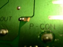
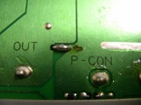
Upon closer inspection while looking for D4 i noticed a blown trace(see picture). I've since repaired the trace but haven't tried to power it up yet. I'm wondering what might have blown the trace in the first place and is it a good idea to try to power it up or should i be looking for something specific. Thanks for all your help so far!
Upon closer inspection while looking for D4 i noticed a blown trace(see picture). I've since repaired the trace but haven't tried to power it up yet. I'm wondering what might have blown the trace in the first place and is it a good idea to try to power it up or should i be looking for something specific. Thanks for all your help so far!
Attachments
Well it seems to be working. I'll have to test it with subs or a dummy load connected. So if i understand it correctly a 12 volt source was probaly touched to the outside of the amp where the paint rubbed off and blew the trace to ground since it was too small for the current traveling through it?
Thanks for all the help, i wish i noticed the issue earlier before wasting peoples time. I'll post the results of a true test tomorrow evening.
Thanks for all the help, i wish i noticed the issue earlier before wasting peoples time. I'll post the results of a true test tomorrow evening.
- Status
- This old topic is closed. If you want to reopen this topic, contact a moderator using the "Report Post" button.
- Home
- General Interest
- Car Audio
- Kenwood KAC-9102D Problems