Cores
The yellow cores look identical to what I used, I superglued two together for each trafo.
I had to experiment as the company that sold me the cores had no idea what they were. (go figure)
The object is to avoid saturating the cores, but to get as much copper as possible on there for good power transfer. if they saturate, the FETS on the primary will see a short. Rather use a bigger core or less copper if not sure.
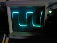
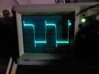
At the beginning I tried to calculate the specifications and flux density etc, but it did not work well at all, I eventually resorted to winding several experimental ones and observing primary winding waveforms on a scope to see when I was approaching the limits. (the square wave will change to something else when nearing saturation) I then backed off a bit, or used bigger cores.
If it's wrong the trafos will get seriously hot with no load, they shouldn't get hot al all if it's right.
I know this is not really scientific but it worked just fine for me, just took a little longer.
The yellow cores look identical to what I used, I superglued two together for each trafo.
I had to experiment as the company that sold me the cores had no idea what they were. (go figure)
The object is to avoid saturating the cores, but to get as much copper as possible on there for good power transfer. if they saturate, the FETS on the primary will see a short. Rather use a bigger core or less copper if not sure.
At the beginning I tried to calculate the specifications and flux density etc, but it did not work well at all, I eventually resorted to winding several experimental ones and observing primary winding waveforms on a scope to see when I was approaching the limits. (the square wave will change to something else when nearing saturation) I then backed off a bit, or used bigger cores.
If it's wrong the trafos will get seriously hot with no load, they shouldn't get hot al all if it's right.
I know this is not really scientific but it worked just fine for me, just took a little longer.
Winding cores
Also at these frequencies you need to use Litz wire as the electrons tend to travel near the surface of the copper wire, so what we want here is plenty of surface area.
(most of the cheap designs use single strand) which defeats the object totally.
If there is bad power transfer in the trafos, then the SMPS is useless, the trafo's and switching frequency are the most important thing if we want to get our 1.5Kw output.
Using many strands of thinner copper wire twisted together is what we want as this both increases the effective surface area and the air gap between the promary/secondary windings which will make it more tolerant of using the wrong or a not 100% correct torroid core.
I used: Primary 8 strands of 0.8mm wire twisted together and secondary 6 strands of 0.8 mm
I wound primary/secondary ratio of 1:4 which equates to about 43 V +/-
theAnonymous1 said:Would either of these cores be suitable for this design? I believe they are T-184 size.
An externally hosted image should be here but it was not working when we last tested it.
the blue ones look identical to the ones I have which are hi-flux types. they are best for output inductors of SMPS's or flyback transformers. not good for push-pull designs. it is basically a more expensive, higher power and lower loss version of the yellow-white powdered iron cores.
Cores
Maybe wind one of each and test em?
Inductors drive me crazy with all of the things that can influence them.
I just powered this puppy up for the first time in 18 Months...
Current draw with no load is about 200ma, and waveforms are looking good. FETS are cold with no heatsink, so I am confident the circuit has no issues.
Output voltage +50 0 -50, put a 600 W load on it, voltage dropped to +47 0 -47
I want to test later for maximum load spec.
What criteria should I use?
Re: Cores
hey ricsmuts,
You used two cores for one trafo? so you got how big cross section of each trafo this way? By doing this trafos are tall too, right? Probably less then input and output caps, which look to be pretty big/tall...
X2. Cores that are not right for power trafo will get hot, even in idle, with no load. Use power material, spread winding/s over whole core (make one or close to one turn around core), it was said that if you wind primary in one direction, secondarys should go in other direction, but keep in mind of flux that each winding is making/using. If you wind all in same direction you probably get better primary to secondary coupling, but end result is lower max power, which is odd to me, but it is how it is.ricsmuts said:
If it's wrong the trafos will get seriously hot with no load, they shouldn't get hot al all if it's right.
I know this is not really scientific but it worked just fine for me, just took a little longer.
hey ricsmuts,
You used two cores for one trafo? so you got how big cross section of each trafo this way? By doing this trafos are tall too, right? Probably less then input and output caps, which look to be pretty big/tall...
Hi
I think 10% lower output voltage at full load as when idle, but constant input voltage, so if input sags a bit, you should calculate what would be voltage(idle) then and lower it by 10% to see when could be max...? Most supply have a lot bigger voltage, but goes down a lot, say from 70 to 50v, at say 1500w, 1R load, constant input I think...something like that
I think 10% lower output voltage at full load as when idle, but constant input voltage, so if input sags a bit, you should calculate what would be voltage(idle) then and lower it by 10% to see when could be max...? Most supply have a lot bigger voltage, but goes down a lot, say from 70 to 50v, at say 1500w, 1R load, constant input I think...something like that
Just checking on the Shotkey diodes
12A with 24A surge
So for continuous draw (50V*12A X2) which is two bridge rectifiers and PSU*2 =2400 Watt Surge 1/2 Sec 4800W
I would still go bigger to 25 or 30A rectifiers (I love over engineering)
The reason I used too many IRFZ44 FETS is I never ever want to see one burn, because IRFZ44 burns forever, white hot and maybe 15 seconds.
So much smoke and it stinks out the whole car, so mine is unlikely to burn. You could maybe use 6 per side safely

SM-2 PCB and silkscreen
If there is significant interest for this SMPS (I called it the SM-2...SM-1 blew up and taught me many lessons) I will produce PCB's with a silkscreen and schematics.
I built this thing nearly two years ago because the only designs on the internet are all very small and I wanted a big SMPS.
If there is significant interest for this SMPS (I called it the SM-2...SM-1 blew up and taught me many lessons) I will produce PCB's with a silkscreen and schematics.
I built this thing nearly two years ago because the only designs on the internet are all very small and I wanted a big SMPS.
I am very interested in this design. I think that the biggest concern I and others have is the magnetics. I would love to see PCB's with a silkscreen and schematics. I have lots of blank pcb material and the materials to etch them.
If we could just figure out what permeability core to use, what the minimum cross sectional area is, what number of turns, and type of wire to use, I think that the rest of the build process would be fairly easy.
I would be glad to help test to find out what core to use, I even have a few cores laying around that might work. If you post the design, I will test what I have and let everyone know the results.
Regards,
David
Cores
Those may work... It's hard to say.
I wish I knew exactly what I used, is there any reliable way to measure them without knowing the specifications...?
I will post exact dimensions and pictures later of the ones I used because they obviously work.
If anybody builds this, I would reccomend using the same winding method I did on similar cores.
Transformer specs
David, I agree with you, if you can email me sometime, we can try work something out.
The magnetics I got correct by trial and error, I need to find a way to measure my cores and windings properly and develop an exact specification.
Using transformers that are different can cause many problems, so the design must go together with a specific trafo specification.
- Status
- This old topic is closed. If you want to reopen this topic, contact a moderator using the "Report Post" button.
- Home
- General Interest
- Car Audio
- Any interest Car SMPS