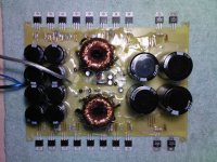
A while ago I designed a real big dual torroid car SMPS with 16 IRFZ 44 fet's powering the two torroids, its unregulated and using a TL494 PWM controller and plenty of capacitance on the PCB.
This thing has served me well and been very reliable.
I havn't done any serious measurements yet but it can draw well over 100 A at 14V so I guess the output is also well over 1200W at 40-0-40V
I am prepared to draw up the schematics, but I first need to know if there's any decent interest?
This thing has served me well and been very reliable.
I havn't done any serious measurements yet but it can draw well over 100 A at 14V so I guess the output is also well over 1200W at 40-0-40V
I am prepared to draw up the schematics, but I first need to know if there's any decent interest?
Aren't those rectifiers just a liiitle bit small to go pushing that much current through? I would have thought TO-247's would be needed. I see no ouput filtering chokes - my guess is you built the trafos with enough leakage reactance so the charging currents of those big-@** caps don't smoke the rectifiers?
Of course we're interested. Especially in the specifics of your magenetics") Frequency, perm, turns, # and guage, leakage reactances....
Frequency, perm, turns, # and guage, leakage reactances....
Of course we're interested. Especially in the specifics of your magenetics
Frequency, perm, turns, # and guage, leakage reactances....Schematic
I am going to have to redraw the schematic as it was lost a little while ago, this will take a little time, so please be patient.
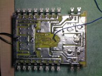
I do still have the layout of the PCB traces I can send you, and can list the components and placement if you like.
I decided to share this design because there is nothing out there of it's size that anybody seems to have published, and this was one of the things I have built I got correct from the beginning. It's alo uses a TL494 like the commercial amps and not the SG chip.
The SMPS is basically a dual supply controlled by one TL494 and the outputs of the two supplies are regulated, filtred and joined at the end, but can be split for two channels if needs be.
It's loosely based on the common commercial circuits by reverse engineering several amps and with some features removed. The duty cycle is 50% unregulated and it runs at +/- 2Khz
This SMPS runs cool, has never overheated, and provides more than enough power for 4 X 15" 800W subwoofers, which was my original design goal, but I may have over engineered this one just a little...
The worst part is winding the torroids, as if the wrong cores are used and they saturate the explosion is quite impressive
I am going to have to redraw the schematic as it was lost a little while ago, this will take a little time, so please be patient.
I do still have the layout of the PCB traces I can send you, and can list the components and placement if you like.
I decided to share this design because there is nothing out there of it's size that anybody seems to have published, and this was one of the things I have built I got correct from the beginning. It's alo uses a TL494 like the commercial amps and not the SG chip.
The SMPS is basically a dual supply controlled by one TL494 and the outputs of the two supplies are regulated, filtred and joined at the end, but can be split for two channels if needs be.
It's loosely based on the common commercial circuits by reverse engineering several amps and with some features removed. The duty cycle is 50% unregulated and it runs at +/- 2Khz
This SMPS runs cool, has never overheated, and provides more than enough power for 4 X 15" 800W subwoofers, which was my original design goal, but I may have over engineered this one just a little...
The worst part is winding the torroids, as if the wrong cores are used and they saturate the explosion is quite impressive
wg_ski said:Aren't those rectifiers just a liiitle bit small to go pushing that much current through? I would have thought TO-247's would be needed. I see no ouput filtering chokes - my guess is you built the trafos with enough leakage reactance so the charging currents of those big-@** caps don't smoke the rectifiers?
Of course we're interested. Especially in the specifics of your magenetics
It very much reminds me of a supply I have from a commercially available amp. It has the same amount of MOSFETs and the same TO-220 rectifier setup. No problems with smoked rectifiers either.
An externally hosted image should be here but it was not working when we last tested it.
Good point on the rectifiers
Havn't blown them yet, but have been waiting for the bang.
The rectifiers are 25A each with surge ratings of about 50A, but output chokes would be an excellent idea, I also omitted to put chokes on the input which should be nescessary I would think.
The TL494 does a soft start which is probably why it's survived.
The only filtering that's added is the RC filter on the output rails- RHS of picture that quenches any ripple above about 30Khz. They do get quite warm, so they must be doing some serious work.
I need everybody's ideas, and then I will redraw the schematic with the improvements.
Stability and safety is what I'm after because when these babys blow, they go into thermo nuclear meltdown till you cut the power.
Re: That PS is interesting
It's from a BOSS PD-4000.....
http://www.realmofexcursion.com/ampguts/Boss_PD-4000/
I've only tested it at ~500w continuous so far after "upgrading" some components.
As you can see in the pic there are no input or output filters, so they must not be too critical. I abused the amp for a few years with no problems before deciding to dissect it.
ricsmuts said:What's it from? Similar layout and I see there is an op amp on that board, looks like a protection circuit.
With all those fets, I think decent size transformers are needed, but I wonder what the minimum is?
It's from a BOSS PD-4000.....
http://www.realmofexcursion.com/ampguts/Boss_PD-4000/
I've only tested it at ~500w continuous so far after "upgrading" some components.
As you can see in the pic there are no input or output filters, so they must not be too critical. I abused the amp for a few years with no problems before deciding to dissect it.
I have completed the design documents for this SMPS
I do NOT have the schematic anymore, but all are welcome to email me for the
1) PCB layout
2) Component list
3) Component layout tagged picture
With this you can build the SMPS just fine
As for the torroinds, I wound them from two smaller cores each, and 6 and 4 strand Litz wire I made myself.
I don't know how to begin to explain how I wound them, it's very complicated to explain here, and better if you have wound similar torroids before, but I will try explain if you email me.
Very nice design Luka
Nice and neat, very nice work!
I still need to post the 2 channel amp I made for this power supply, not my own design but another modified one using 20X TIP35/36C Transistors, 10 Per channel.
It's a similar layout to the power supply and the two are designed to fit in the same chassis.
Nice and neat, very nice work!
I still need to post the 2 channel amp I made for this power supply, not my own design but another modified one using 20X TIP35/36C Transistors, 10 Per channel.
It's a similar layout to the power supply and the two are designed to fit in the same chassis.
Hi
Thanks...
One more thing, I think I will be easyer for you if you post those things, PCB and all, since I thing there will be many people asking for it
Few things I would like to know:
1. what is the freq.
2. is that 1mm wire
3. do you really need 8 fets pet trafo (since each IRFZ an let say conduct 35A, 8test on whole board at conduction at same time = 8x35A * 12v = many kw) When you say it was over build you weren't kidding aroung, fets alone can cost much... Nice job again
Thanks...
One more thing, I think I will be easyer for you if you post those things, PCB and all, since I thing there will be many people asking for it
Few things I would like to know:
1. what is the freq.
2. is that 1mm wire
3. do you really need 8 fets pet trafo (since each IRFZ an let say conduct 35A, 8test on whole board at conduction at same time = 8x35A * 12v = many kw) When you say it was over build you weren't kidding aroung, fets alone can cost much...
Nice job againWould either of these cores be suitable for this design? I believe they are T-184 size.
An externally hosted image should be here but it was not working when we last tested it.
- Status
- This old topic is closed. If you want to reopen this topic, contact a moderator using the "Report Post" button.
- Home
- General Interest
- Car Audio
- Any interest Car SMPS