 . One can compare then...
Testing
Tried to do some testing to full power, with an amp connected, got to about 800W the amp went into thermal runaway (my fault) and had all 16 of the smps's IRFZ44 burn out!
I found this rather odd....
What a mess...
It's a whole heap of components I now have to replace, but I guess it comes with the territory.
Re: Schematic
Thanks.
Any luck on converting the layout to PDF yet?
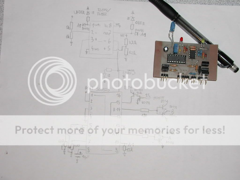
ricsmuts said:Finally, here is the schematic.
Thanks to Nejc for preparing this.
Thanks.
Any luck on converting the layout to PDF yet?
The IRFZ44 is a FET which is a voltage controlled device and not a current controlled device therefore big driver components such as are needed with BJT's are not necessary or required when using them.
FET's are mostly glorified switches with miniscule drive currents and very low on resistances, which is what make them ideal for power supplies and anything using PWM, and you can parallel tens of them very easily because of this.
Those are the good things, the bad ones are, they love to oscilate, they are also totally unstable untill situated in their circuits and are susceptable to damage with static and gate capacitances can cause all kinds of things to happen as well.
There are four resistors and four transistors that handle the turn on/turn off by means of switching the voltage between 0V and 12V, drive current is almost a non issue here.
Buffer Transistor or not the rise time of the TL itself won't change.
I do however understand your point and what you are getting at, The only thing I can think of that would significantly help speed the rise time would be to use darlingtons as the buffers.
You would need pulldown/up anyhow.
This design was partly reverse engineered from a cheap amp and they used the minimum components in the original design.
The trigger signals are very clean already so I felt no need to change it. Show me this circuit you are thinking of, I may put it in, always open to suggestions.
I understand the circuit, but would you not still have to drive the input low and be back where you started?
It's already producing a perfectly good square wave gate drive near 0/12v
If Perry is right the TL494 won't drive it low, if it has a small pulldown then it still may work.
Becaus I'm now curious, I need to go look at the data sheet for the TL494 again.
It's already producing a perfectly good square wave gate drive near 0/12v
If Perry is right the TL494 won't drive it low, if it has a small pulldown then it still may work.
Becaus I'm now curious, I need to go look at the data sheet for the TL494 again.
This is a 494 driving a 2200pf load. You can see that the rise time is fast but the falling edge of the waveform is not square. Driving the voltage high is not problem but it needs help to get the voltage down quickly enough to prevent having both banks of FETs on at the same time. This is the reason that you don't 'need' a driver transistor to drive the gates high but you need a PNP driver transistor to pull the gate voltage down.
http://bcae1.com/temp/P1010122b494driving2200pfload.jpg
There is a limit to the current it can produce to drive the output high but it generally won't have a problem with driving 3-4 FETs (FETs with relatively low Ciss) high without an NPN driver transistor.
http://bcae1.com/temp/P1010122b494driving2200pfload.jpg
There is a limit to the current it can produce to drive the output high but it generally won't have a problem with driving 3-4 FETs (FETs with relatively low Ciss) high without an NPN driver transistor.
If you look back at the scope traces I posted, (page 2 of thread) there is a very slight trail off on the pulldown. (similar)
Possibly I should look at driving it off harder. On the same scope trace is a quirk in the middle of the rise and fall I am not sure where it is comming from.....
Possibly I should look at driving it off harder. On the same scope trace is a quirk in the middle of the rise and fall I am not sure where it is comming from.....
- Status
- This old topic is closed. If you want to reopen this topic, contact a moderator using the "Report Post" button.
- Home
- General Interest
- Car Audio
- Any interest Car SMPS