we have a problem here.....
I did some calculations based on the formulas eva posted here before and the results surprised me....
(80V is rails at 13.8V input, 104V is rails at 18V input)
1pc Material 60 T150
area: 0.887cm2
volume: 8.31cm3
mag lenght: 9.38cm
turns: 44
inductance: 125uH
B=666.188378 gauss @ 80V
B=866.044892 gauss @ 104V
H= 235.779957 Oe @ 80V
H= 306.513944 Oe @ 104V
est. core loss 80V = 2.05W
est core loss 104V = 2.67W
2pcs Hi Flux T106 stacked
total area: 1.318cm2
total volume: 8.56cm3
mag lenght: 6.49cm
turns: 22
inductance: 177uH
B=1557.63gauss @ 80V
B=2031.70gauss @ 104V
H=170.386441 Oe @ 80V
H=221.502373 Oe @ 104V
est. core loss 80V = 6.93W
est. core loss 104V = 9.04W
2pcs MPP T130 stacked 66nH/t2
total area: 1.396cm2
total volume: 11.56cm3
mag lenght: 8.28cm
turns: 37
inductance: 177uH
B=5033.69gauss @ 80V
B=6543.79gauss @ 104V
H=224.609 Oe @ 80V
H=291.99 Oe @ 104V
est. core loss 80V = 13.96W
est. core loss 104V = 18.16W
so it looks like I really have to buy the original cores for the amp and the MPP ones will be much worse than the hi-flux. big problem is I don't know where!!!!
edit: I'm not sure if I computed the core loss correctly since I can't find a graph so I indicated "est." (estimated) as I just put together a formula using ratio and proportion to come up with an answer.
yup. all input and output PS caps are rated to handle that. 18V is used by dbdrag competitors. I just wanted to be sure that I have enough margin to operate safely and when I decide to sell this, that I know it will operate as the original amp did.
I measured 14.2V highest in my car. drops to 13.8V most of the time.
my problem right now is that I looked on all online sources that I could think of and none of them carries the -60 material. looks like I'm going to request a sample or go to the micrometals factory directly if all else fails. (I'm going to the US sometime in july or august)
Eva, I need help here. surely you must know a place that sells -60 material.
I measured 14.2V highest in my car. drops to 13.8V most of the time.
my problem right now is that I looked on all online sources that I could think of and none of them carries the -60 material. looks like I'm going to request a sample or go to the micrometals factory directly if all else fails.
(I'm going to the US sometime in july or august)Eva, I need help here. surely you must know a place that sells -60 material.
I rechecked the computations again as MPP should be a low loss core but it was highest?  also, I found graphs for B versus freq losses so I added some more except for hi-flux as I couldn't find any...
1pc Material 60 T150
area: 0.887cm2
volume: 8.31cm3
mag lenght: 9.38cm
turns: 44
inductance: 125uH
B=666.188378 gauss @ 80V
B=866.044892 gauss @ 104V
H= 235.779957 Oe @ 80V
H= 306.513944 Oe @ 104V
graph based, 80V = 11.634w
graph based, 104V = 19.94w
2pcs Hi Flux T106 stacked
total area: 1.318cm2
total volume: 8.56cm3
mag lenght: 6.49cm
turns: 22
inductance: 177uH
B=896.675gauss @ 80V
B=1165.678gauss @ 104V
H=170.386441 Oe @ 80V
H=221.502373 Oe @ 104V
graph based, 80V = ??
graph based, 104V = ??
2pcs MPP T130 stacked 66nH/t2
total area: 1.396cm2
total volume: 11.56cm3
mag lenght: 8.28cm
turns: 37
inductance: 177uH
B=503.369gauss @ 80V
B=654.379gauss @ 104V
H=224.609 Oe @ 80V
H=291.99 Oe @ 104V
graph based, 80V = 2.08w
graph based, 104V = 3.70w
looks like I can use the MPP cores that are coming here.
also, I found graphs for B versus freq losses so I added some more except for hi-flux as I couldn't find any...1pc Material 60 T150
area: 0.887cm2
volume: 8.31cm3
mag lenght: 9.38cm
turns: 44
inductance: 125uH
B=666.188378 gauss @ 80V
B=866.044892 gauss @ 104V
H= 235.779957 Oe @ 80V
H= 306.513944 Oe @ 104V
graph based, 80V = 11.634w
graph based, 104V = 19.94w
2pcs Hi Flux T106 stacked
total area: 1.318cm2
total volume: 8.56cm3
mag lenght: 6.49cm
turns: 22
inductance: 177uH
B=896.675gauss @ 80V
B=1165.678gauss @ 104V
H=170.386441 Oe @ 80V
H=221.502373 Oe @ 104V
graph based, 80V = ??
graph based, 104V = ??
2pcs MPP T130 stacked 66nH/t2
total area: 1.396cm2
total volume: 11.56cm3
mag lenght: 8.28cm
turns: 37
inductance: 177uH
B=503.369gauss @ 80V
B=654.379gauss @ 104V
H=224.609 Oe @ 80V
H=291.99 Oe @ 104V
graph based, 80V = 2.08w
graph based, 104V = 3.70w
looks like I can use the MPP cores that are coming here.
All your calculations seem right...
2pcs Hi Flux T106 stacked
total area: 1.318cm2
total volume: 8.56cm3
mag lenght: 6.49cm
turns: 22
inductance: 177uH
B=896.675gauss @ 80V
B=1165.678gauss @ 104V
H=170.386441 Oe @ 80V
H=221.502373 Oe @ 104V
graph based, 80V = approx. 9W (outside table)
graph based, 104V = approx. 18W (outside table)
This is assuming a 147u Hi-Flux core (Arnold HF-106147-2) which is the one that results in approx. 177uH inductance with 22 turns and 2 cores stacked.
----------------------------------------------------
2pcs MPP T130 stacked 66nH/t2
total area: 1.396cm2
total volume: 11.56cm3
mag lenght: 8.28cm
turns: 37
inductance: 177uH
B=503.369gauss @ 80V
B=654.379gauss @ 104V
H=224.609 Oe @ 80V
H=291.99 Oe @ 104V
graph based, 80V = 1.4w (for 60u Arnold A-071065-2)
graph based, 104V = 2.3w (for 60u Arnold A-071065-2)
In other words, cool
----------------------------------------------------
The problem that you are going to have with 60u MPP is that inductance drops to 50% at H=100 Oe and to 20% with H=200 Oe, so the amplifier may not like very low impedance loads (2 ohms). 26u is more suitable for that purpose because inductance drops to 70% at H=100 Oe and to 50% at H=200 Oe. Anyway, your 60u arrangement is ok for 4ohm operation. 50% inductance drop at full peak output current is ok.
Congratulations for understanding all the calculations, particularly H which is very important for sizing the output inductor of any class D amplifier to handle the maximum output current imposed by supply rails and rated load.
I don't know "60" material either, but an output inductor should never idle near 90ºC. This is a very bad design practice. Iron powder cores suffer from thermal aging, they progressively lose their permeability and the hotter they operate the faster it happens. A badly designed inductor can become useless within a few months or years.
oh no!!!
I need that amp to be able to run at 2ohm full power. the online sources you posted doesn't seem to have the 26u MPP cores. any idea where I could get some? the 60u ones are from the ebay page you posted a while ago...
I'll do a bit more computation if I could lower H value to less than 200 since the amp originally has 125uH inductance and I increasd it since I thought the increased inductance could take care of the drop at high currents.
edit: with 30 turns, we get about H = 180 at 80V and about H = 240 at 104V so we are still above but a little lower.
core losses will definitely be higher but probably not burning hot.
I need that amp to be able to run at 2ohm full power.
the online sources you posted doesn't seem to have the 26u MPP cores. any idea where I could get some? the 60u ones are from the ebay page you posted a while ago...I'll do a bit more computation if I could lower H value to less than 200 since the amp originally has 125uH inductance and I increasd it since I thought the increased inductance could take care of the drop at high currents.
edit: with 30 turns, we get about H = 180 at 80V and about H = 240 at 104V so we are still above but a little lower.
core losses will definitely be higher but probably not burning hot.
The original inductor was probably not able to handle 2 ohms either. The chance to see an output inductor failing is almost non existent unless there is something wrong with the design.
20% of 177uH is still 35uH which isn't too bad at 77Khz when the output approaches the rails. Using many turns always helps because you end up with higher inductance despite the higher drop due to stronger H. This is good as long as the control loop remains stable across the resulting inductance range, which is something that you should test. Resonance of the first LC section would rise from 3800Hz to 8500Hz when inductance drops from 177uH to 35uH. What are the LC values in the second section?
Which switching MOSFETs and how many are employed in the class D section and in the PSU? How much current is required to trigger the protection? Is the circuit really sized to handle 40A-50A peak?? I have serious doubts. Those fashion class D amplifiers are not that good.
Anyway, consider finding some free space to add one or two stacked core(s) near the first pair and wired in series. The hot (switching) end should be connected to the first pair (short wire to avoid EMI).
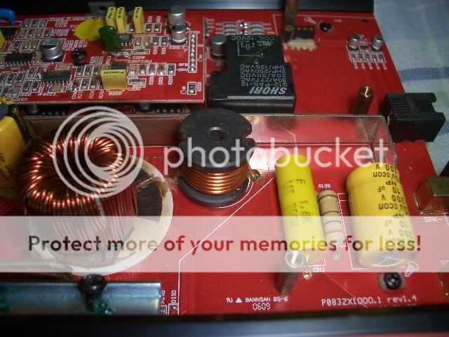
first LC section (originally) is 125uH and 10uF. the next one is an unlabeled drum core inductor and 1.8uF film cap with a 2R + 10uF zobel.
main fets are a two pairs of IRFP264N. I don't know the overcurrent limit.
PSU uses 4 pairs of IRF3205, 2" diameter main trafo, 4X 820uF 160V per rail, rectifiers are F30D40D.
I'm suspecting that the original inductor failed because the windings rubbed and shorted or that it got hot enough that the varnish melted off and shorted to each other.
how do I test the stability of the control loop when everything is installed? does it have to be loaded? pushing full power? what do I look for? I have a sine/square wave signal gen so I could use that. no high power dummy loads though.
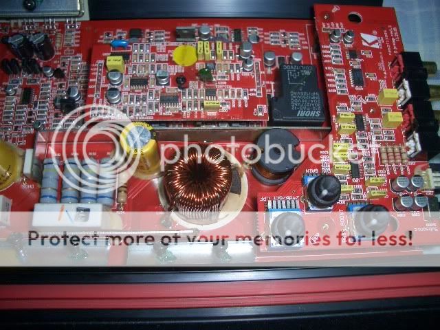
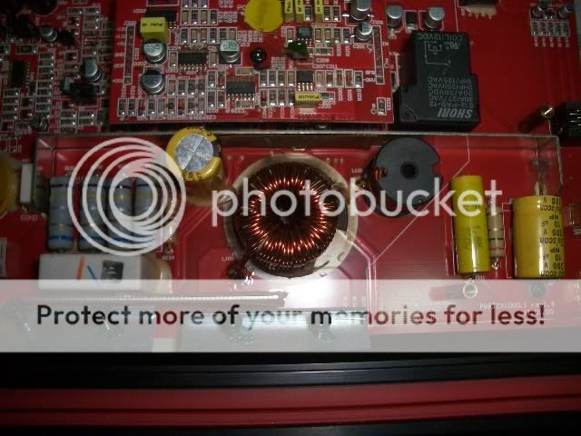
here are some latest pictures of the amp. it still has the T106-125perm hi-flux cores installed.
main fets are a two pairs of IRFP264N. I don't know the overcurrent limit.
PSU uses 4 pairs of IRF3205, 2" diameter main trafo, 4X 820uF 160V per rail, rectifiers are F30D40D.
I'm suspecting that the original inductor failed because the windings rubbed and shorted or that it got hot enough that the varnish melted off and shorted to each other.
how do I test the stability of the control loop when everything is installed? does it have to be loaded? pushing full power? what do I look for? I have a sine/square wave signal gen so I could use that. no high power dummy loads though.
here are some latest pictures of the amp. it still has the T106-125perm hi-flux cores installed.
If the loop is stable, you will get clean sinewave output (no 500Hz-10Khz ringing) and clean clipping with and without load.
This amplifier was never designed to reliably drive 2 ohms, take a look at the datasheet of IRFP264N, max allowed drain current is 44A at 25ºC and 31A at 100ºC. Also, 40A output current is reflected back to the primary as 66A per IRF3205, which is a bit high (not to mention 50A which results in 83A per IRF3205).
The amplifier probably blew because it was driving hard a 2 ohm load, and it will probably blow again in the same conditions.
Couldn't you measure the pot inductor? I doubt this one can handle 40A either, it's very likely to saturate at 25A or less given the size.
The current limit has probably a lot to do with those four grey resistors.
the amp may not work with full power but will probably be fine with music?
I think power loss from battery voltage sag/cable loss/SMPS output sag are also factors that prevent this amp from blowing up when driven hard into 2ohms. just note that the 80V rails are unloaded so they will definitely be lower when driving a speaker.....
the four resistors are indeed for the current limit sense but I have no idea what the values are since the color codes don't make any sense. also, I don't have any means to measure very low resistances.
IRFP264 is 31A at 100degC that is per fet right? this has four. two per rail and is running half bridge so it should be within limits.
I could take out the inductor and measure it but it would be a lot of work. I'll try to take it out and post later.....
edit: the inductor is glued in pretty tight so I can't remove it without fear of breaking it.
- Status
- This old topic is closed. If you want to reopen this topic, contact a moderator using the "Report Post" button.
- Home
- General Interest
- Car Audio
- Kicker ZX1000.1 repair