I bought this ZX1000.1 amp broken for about $100 (I know, not the best of deals but there's something to practice on. ") )
)
so the story of the previous owner is that he is using it and it just stopped playing then it let out the magic smoke. after that, it still powers up but there's no sound.
pictures are in here.
so for the limited time to check the amp, here's what I have found out:
-output inductor is cooked to a crisp. I assume the windings scraped and shorted to each other.
-PS fets are all toast. I'm assuming the output inductor caused this failure?
-main PS fet gate drives all still work so I guess that is good news.
-aux PS still runs nicely.. again, more good news.
-speaker relay clicks and timing is as it should be.. some more good news.
-output fets aren't shorted from G-S terminals.. I'm hoping they're all good so this is good news?
**after cleaning and removing the burned FR4 areas, I'm left with a big gaping hole in one of the FET positions. I was thinking of leaving this hole and mounting the FET sort of point to point. is this a good idea?
**the output inductor is severely burned. I was thinking the core is toast so I want to replace it with an MPP core that I ordered. (same size T-130) anyone know the inductance value of this coil?
**before I spend on IRF3205's, I was thinking of installing IRFZ44's to test run the amp and see if the class D modulator works. is it safe to run this amp without the heatsink?
)so the story of the previous owner is that he is using it and it just stopped playing then it let out the magic smoke. after that, it still powers up but there's no sound.
pictures are in here.
so for the limited time to check the amp, here's what I have found out:
-output inductor is cooked to a crisp. I assume the windings scraped and shorted to each other.
-PS fets are all toast. I'm assuming the output inductor caused this failure?
-main PS fet gate drives all still work so I guess that is good news.
-aux PS still runs nicely.. again, more good news.
-speaker relay clicks and timing is as it should be.. some more good news.
-output fets aren't shorted from G-S terminals.. I'm hoping they're all good so this is good news?
**after cleaning and removing the burned FR4 areas, I'm left with a big gaping hole in one of the FET positions. I was thinking of leaving this hole and mounting the FET sort of point to point. is this a good idea?
**the output inductor is severely burned. I was thinking the core is toast so I want to replace it with an MPP core that I ordered. (same size T-130) anyone know the inductance value of this coil?
**before I spend on IRF3205's, I was thinking of installing IRFZ44's to test run the amp and see if the class D modulator works. is it safe to run this amp without the heatsink?
The inductor is probably ~50uH but that's a guess.
Do you have an inductance meter?
If not, can you borrow one?
If you have access to one and the inductor is shorted, unwind it (count the number of turns). Re-wrap it with 3-4 turns and measure the value. Do the same with your MPP core. If they both have essentially the same value with 3-4 turns, re-wrap the MPP core with the same number of turns as the original. If they have significantly different values, the easiest option would be to re-wrap the original core with the original number of turns (not necessarily the same number of strands - a single strand will suffice) and measure the value. Then wrap the MPP core with whatever number or turns you need to get to the correct value.
I'd recheck the outputs, they're likely shorted. Check all of them individually. Check from gate to drain as well as from drain to source.
You can go point to point but I'd suggest using tinned/filled desoldering braid instead of wire.
Monitor the temperature of the semiconductors when you power it up out of the sink. If they don't run too hot, it's safe (but you need to continuously monitor their temperature).
thanks for the reply.
yup, I do have an inductance meter. as of now, the MPP cores haven't arrived yet so all I could do is probably rewind the core and use it temporary for testing.
I just did a quick test with the output fets still on board. the meter on continuity test and all combinations (G-S, G-D, D-S, and repeating with reversed probes) did not indicate any short. I might try removing them from the board tomorrow and testing again if needed. all gate resistors are good.
fortunately, in the PS fet place with the big hole, the fet drain lead can still reach the drain pad connection and the source pad still intact. but the gate pad, gate resistor pad and all the FR4 around it is gone. might have to P2P that one.
I'm assuming the failure of the PS fets were because they were mixed. the fets have different batch codes and are mixed together in the two groups. there hasn't been any evidence of previous repairs so they are original.
I powered it up today using a temporary powdered iron toroid of 80uH about the same as the original which I rewound (still drying the varnish coating that I applied) and using only one pair of IRFZ44's on the primary.
I got a clean 76.9kHz square wave output right before the output inductor but the IRFZ44 fets are heating up when powered.
input current draw peaks at more than 5A (5A is the max on my PS ammeter) and stabilizes at 3A idle. I applied a sine at the input with no load at the output and I got a sine output as expected. I'm afraid of testing it with a load as the temporary PS fets might blow up.
edit:
there is 2Vpk-pk sine wave residual at output and the temporary inductor got a little hot (not unexpected as it is a low freq powder iron toroid)
If you have a good, clean gate drive signal on the Z44s and the drive signal goes to ground between pulses, they're likely getting hot because only 2 are taking the entire load.
3A of current draw is higher than I'd expect to see. It may go down when you replace the inductor.
2vp-p is a little high but it may not be more than normal. Assuming that one speaker terminal goes to the secondary ground, connect the short scope ground (the one that connects to the probe) to the negative speaker terminal and measure the residual again. It will likely be much lower. Do this with a speaker/dummy load connected.
I forgot to check the gate drive with the fets connected but they are clean when I checked them without any fets.
the residual is measured with the scope gnd connected to the ground bus bar which connects the speaker ground to the capacitor bank center tap.
if it is a little high, I think it might have something to do with the first 10uF NP cap right after the inductor which is part of the LPF. it might have been cooked since it was beside the inductor that got really hot.
also, I measured the residual right after the first inductor. there is still another inductor and capacitor (making a 4th order filter) right before the speaker relays then the output terminals.
will do some more measuring when I get the rewound core back into the amp.
gate drive waveform is normal. except that it is around 10Vpk. voltage on the totem pole collectors are normal at gnd and 13.8V, input to the bases are 12Vpk (from the TL594)
the fets still get hot, the OEM output inductor also gets hot. input current draw is about 2.8A. I'm thinking this inductor is really meant to run hot. I rewound it with higher temp magnet wire but I'm still tempted to replace it with MPP to make it run cooler for reliability reasons...unfortunately, I misjudged the core size. OEM core is T154 and the MPP I have is T130. I might try a double stack core?
at startup, the gate drive is a little unusual. deadtime is constant, amplitude slowly ramps up from around 2V to 7V then as the speaker relay engages, it instantly goes to 10Vpk and stays there.
residual right before the speaker relay is 0.4Vpk-pk sine, that's without any load connected.
I have a dilemma.....
I bought eight replacement fets and they look rather different from the IR fets I currently see. probably an old stock? I got them for about $2 each.
there are two batch codes. three and five of each so I guess a proper paralleling with same batch codes ain't gonna happen here. I should have bought ten.
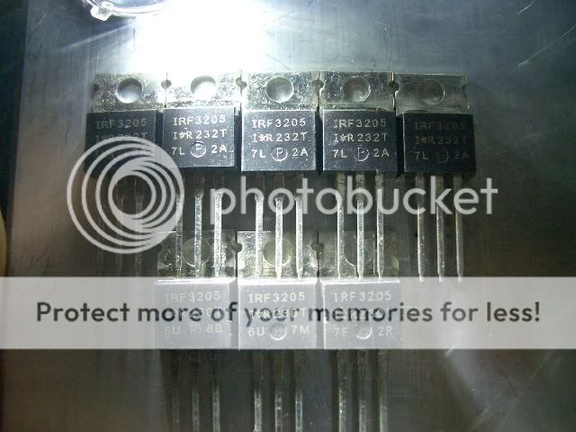
I assumed the PS failed due to different fet batch codes.... I looked more closely and saw that the original fet prints looked different from each other but the date code is the same. how could that be?
here's a picture of the old fets along with the new ones I bought....
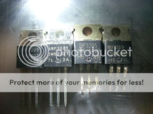
what am I gonna do now?
I bought eight replacement fets and they look rather different from the IR fets I currently see. probably an old stock? I got them for about $2 each.
there are two batch codes. three and five of each so I guess a proper paralleling with same batch codes ain't gonna happen here.
I should have bought ten.
I assumed the PS failed due to different fet batch codes.... I looked more closely and saw that the original fet prints looked different from each other but the date code is the same. how could that be?
here's a picture of the old fets along with the new ones I bought....
what am I gonna do now?
All 3 at the bottom are different. They were produced during the same week but are not from the same batch. From the codes on the transistors, it appears that they were produced in weeks 30 and 32 of 2002.
If you purchased them from a local supply house, go back and get 4 more that match.
You use a lot of parts. You should order these in full sticks (50 pcs) so you'll have plenty with matching date codes. Some suppliers will ship only those with matching date codes if you tell them you need matching codes when you order the parts. At higher quantities, they are generally less expensive (less than $1US).
went back to the local store and unfortunately they only had two left.
the good thing though is that they match the five others in the previous order so I have seven similar fets and three different ones.
I'm gonna take my chances on this one and hopefully pick the best one of the three....
the good thing though is that they match the five others in the previous order so I have seven similar fets and three different ones.
I'm gonna take my chances on this one and hopefully pick the best one of the three....
ok, so I powered it up for about 3-5min and the PS fets get a little warm without any heatsinking. well, not really that warm. just perceptibly warm. but everything else seems fine.
I went ahead and installed it in the heatsink for further testing as the voltage regulators are getting hot without any cooling and powered it up and played music.
everything runs as normal. output before the output filter is a nice square wave but the first output inductor is getting quite hot and the smell of varnish is coming out of it. it was hot to touch and I couldn't keep my finger on it for a second.
also, the first capacitor (10uF 200V NP) connecting the inductor output to ground is also getting warm.
looks like the inductor core material is toast and I need to replace it?
square wave peak is similar to rail voltage = 80V more or less... nice square without any spikes or ringing. although there is a little slope on the tops. the sides (turn on and off slopes) are perfectly vertical but the tops are slightly sloping and gradually increasing before the fets turn off. did you get what I mean?
after the inductor, it is a sine wave at about 2Vpk-pk
PWM is 76.9kHz at idle.
edit: gate drive is about 10-11Vpk at 13.8V input. I think it is a tad lower than I would like. is that normal with amps using TL594 and totem pole drivers?
also, four IRF3205's a side should have a lot of current carrying capacity so they should stay completely cool even without heatsinking with 3A continuous draw so I would think something must be wrong at the PS section
Looking at the signal on the gate leg of the PS FETs, you'll probably see a tiny pulse on the falling edge of the waveform. If the pulse occurs before the FETs switch off (~3.3v), the FETs will run hot. The pulse occurs when the other bank of FETs turns on. If both banks of FETs are on at the same time, they will run hot. Does the gate voltage drop below 3v before the pulse.
In this photo, you can see the pulse occurs at ~4v on the bottom waveform (gate leg of FET). This was causing the FETs to run hot.
http://bcae1.com/temp/psP1010089b.jpg
In this photo, you can see the pulse occurs a bit lower than 3v. This was taken after the drivers were replaced.
http://bcae1.com/temp/psP1010091b.jpg
Less than 1v of ripple shouldn't make the capacitor heat up. It may be defective also.
Is there any DC on the output?
I removed the driver transistors and tested them with diode check on the DMM and all of them checked OK.
it might be due to the fact that I'm using an earlier version of '3205's that have higher gate charges? the gate resistors are rather high at 100ohms.
I could either replace the gate resistors with lower values (which I'm not sure as I don't have lower resistance SMD resistors here and they aren't available anywhere) or I could increase deadtime?
- Status
- This old topic is closed. If you want to reopen this topic, contact a moderator using the "Report Post" button.
- Home
- General Interest
- Car Audio
- Kicker ZX1000.1 repair