Need a little assitance from an experianced Class D person.
I have an Mmats 3000.1 amp, that came in for repair that had 12 blown 3205's...
replaced the 3205's and the drivers, amp works fine...
Gave it back to the guy and he says it doesn't have near the power as it used to.
So I looked at it again, and BOTH power supplies are functioning, and the only thing i can come up with is that the rail voltage is only +/- 60 volts. The power supply caps are rated for 80 volts DC and the engine is the HIP4080.
I am think that perhaps the rail voltage is supposed to be higher?
The rail voltage should be 80v.
The regulation is controlled by the error amp on the 3525. Pin 2 is tied to the 5v reg. Pin 1 is connected to the center of a voltage divider. R37 goes to the rail. R36 goes to ground. The duty cycle is reduced when pin 1 approaches the voltage on pin 2.
If you have 5v on both pins, the voltage divider may have out-of-tolerance resistors. If the voltage is low on pin 1, another input on the IC may be causing the low duty cycle.
There's no negative rail in these amps.
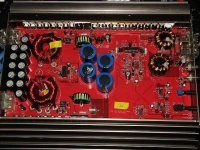
The amp I'm referring to has 16 FETs in the supply so I'm not sure that we're looking at the same amps.
The regulation is controlled by the error amp on the 3525. Pin 2 is tied to the 5v reg. Pin 1 is connected to the center of a voltage divider. R37 goes to the rail. R36 goes to ground. The duty cycle is reduced when pin 1 approaches the voltage on pin 2.
If you have 5v on both pins, the voltage divider may have out-of-tolerance resistors. If the voltage is low on pin 1, another input on the IC may be causing the low duty cycle.
There's no negative rail in these amps.
The amp I'm referring to has 16 FETs in the supply so I'm not sure that we're looking at the same amps.
Attachments
The amp I have here has...
R36 = 4,750 ohms (4751)
R37 = 68,100 ohms (6812)
This produces 80v rails (79.97v calculated from the values of the resistors and the 5.1v reg voltage)
Yours is supposed to produce lower voltage if the resistors are original values. The voltage should be 61.25v from the values you have. That's using 5.1v as the voltage on pin 2.
In this amp, the 4.75k reads 4.4k in the board. The 68.1k reads low but that's because of the large filter caps.
If you change it to a 68.1 k, you should get 80v rails if there's enough ratio on the transformers.
The outputs in this amp are IRF4710s. If yours are a less robust transistor, the higher rail voltage could cause reliability issues.
There seem to have been several different versions of this amp. I'm not sure if one had the lower rail voltage. I have photos of 2 amps that are significantly different but both have the 68.1k resistor.
If the 52.3k resistor was in the amp before it failed, the amp is likely performing precisely as it did before.
If the 68k didn't give you 80v, the transformers may have a lower ratio than the ones I've seen.
Did the voltage on pin 1 reach the voltage on pin 2?
If it's lower, the amp probably wasn't designed to operate at 80v. I'm assuming that the B+ input voltage is not below 12v and the power supplies are in good working order.
Did the voltage on pin 1 reach the voltage on pin 2?
If it's lower, the amp probably wasn't designed to operate at 80v. I'm assuming that the B+ input voltage is not below 12v and the power supplies are in good working order.
It appears that the 4.75k may be out of tolerance.
When the voltage on the 4.75k resistor is 5v, the current through it should be 1.05ma.The current should be the same through the 68k resistor. That should produce 71.8 volts across the 68.2k resistor. The rail voltage should be 76.8v. (71.8+5 ). If the voltage on pin 2 is 5.1v, the regulated voltage should be 78.3v.
If the voltage on pin 2 is not exactly 5v or if the 4.75k resistor is out of tolerance, either could cause the rail voltage to vary from the calculated values.
- Status
- This old topic is closed. If you want to reopen this topic, contact a moderator using the "Report Post" button.
- Home
- General Interest
- Car Audio
- Mmats 3000.1