stuck on this one... 
1. how much power would each sub see?
2. what ohm would best suit the middle sub to make things as even as possible between the three...and would it be truly even?
3. how many ohms would each amp see?
4. would one rail work harder than the other rail?
5. is this a stupid idea?
each amp puts out 600watts@ 4ohm mono (maybe a bit more)
thanx
1. how much power would each sub see?
2. what ohm would best suit the middle sub to make things as even as possible between the three...and would it be truly even?
3. how many ohms would each amp see?
4. would one rail work harder than the other rail?
5. is this a stupid idea?
each amp puts out 600watts@ 4ohm mono (maybe a bit more)
An externally hosted image should be here but it was not working when we last tested it.
thanx
I would never strap amps like that unless I knew exactly what I was doing with a particular amp. I never touch outputs of different amps. I would say get 2 ohm subs so you don't have to do that, or something like that instead of hooking them together. Often that will produce smoke from the amps from what I have seen. You could run different amps to different VCs of same sub, but that chart does not look right.
A, I am not sure that it would actually work with the centre woofer.
B, I would mot do that because if there is any diferences between the amps and there will be they will be fighting each other on the same coil.
C, WHY?
Are these amps 2 ohm mono stable?
Why not run 1 sub at 8ohms on each amp bridged, it will still be 300wrms (assuming they are 2x150@4 ohms) and will have a higher damping factor than running at lower impedance so iwould work very well....
jol50......im not actually strapping the amps...
--------------------------------------
junglejuice, Today i tried 2 amps at 8 ohm mono each, it was just slightly louder and a bit tighter than one amp at 4ohm...maybe about 10% louder than one amp at 4 ohms, and got just as hot...low notes didnt have as much authority...as long as things are within 0.100 volts of each other it should be ok.
-------------------------------------
Perry, im trying to figure out how many ohms each amp will see, since only 1 extra polarity terminal is hooked up, is the amp truly seeing another 4 ohm load (if the middle speaker was 4+4?)
when i measure the voice coil plus one extra polarity , the load still reads 4 ohms...but i think i should hook up 3 coils and measure it again.
would i have to tie together all 4 amps secondaries, or each pair that are seeing a common coil?
would i have to tie together the secondaries leg per leg? does the auxillary supply for the ps drive circuit have to be tied together also?
tying the secondaries together has me thinking now...would this make it possible to truly strap the amps together in parrallel? just curious.
------------------------------
ECM,remember the email i sent telling you it had been fixed bro?...i just didnt have a chance to test it after repair because i didnt have any insulators. the amp had an smp60n06 in place of the 16amp negative rectifier...factory defect i guess.
1 out of the 4 amps is way louder than the others...i think this is mainly do to the emitter resistor value change and the modified transistors used in the predrive/drivecircuit....the output transistor change shouldnt make this much difference (75watt vs 90watt) or should it?
all fets are the same for all amps, those 3205's are kickass, thanks Perry!
With 4 ohm coils, this would essentially be a 2 ohm mono load for the channels connected to the third speaker.
You would have to strap the amps together that were driving a common voice coil. You would tie the center-taps together, not the rails.
You wouldn't want to tie the rails together. If one output section failed, it could destroy both power supplies if the fuses didn't blow quickly enough.
You would have to strap the amps together that were driving a common voice coil. You would tie the center-taps together, not the rails.
You wouldn't want to tie the rails together. If one output section failed, it could destroy both power supplies if the fuses didn't blow quickly enough.

system plans keep changing, just exploring options to maximize power per sub.
i can fit 2-3 subs in the trunk and stay in the consumer class with the power i have and be competitive.
if i enter the 4 sub category, im not sure if i will have enough power to be competitive...and will have to enter the pro class do to no backseat...
if i go for 4 subs 4 amps i have to buy 4 new coils and do more testing to match the spiders and Mms...
besides this, i would love to be still be able to look out the back window.
Yeah, I got that email, but wasn't sure if you had put it thru it's paces. I'm confused as to why one amp would be louder than the rest. Measure the rail voltages on all the amps. Maybe one has a little higher voltage.
Can you stuff a couple of DVC 15" subs and wire one amp to each coil? Or how about 18" subs?
Can you stuff a couple of DVC 15" subs and wire one amp to each coil? Or how about 18" subs?
the amp thats louder has these installed:
BD909/910 outputs
BD909/910 predrive/drive circuit with legs bent around
TI opamps
0.1 ohm emitter resistors
3205 fets in PS
new rail caps, but 85 degree because thats all i had laying around.
it may be the drive signal thats cleaner and not clipping as early as the MPSU...making it seem louder...this amp has more girth... rear view mirror rotates more.
two things i know made a difference are the fets and opamps, im going for the emitter resistors then predrive/drive after that.
soft start circuit on all amps have been disabled.
ive since changed the fets and opamps in the other amps as well as the tantulums and potentiometers so they all match.
i'll measure the power soon with a 60hz tone.
darn internet connection got cut off...
cant fit 15's in the trunk and be effective...not enough space to accomodate proper port flow.
when i finally had a chance to test that amp i ended up blowing a bank of fresh fets because the securing rails couldnt be tightened down enough do to stripped holes in the heatsink....
i gambled and i paid... so i rebuilt the PS again for good measure.
Before you start changing emitter resistors and what not, I would measure the rail voltage on all the amps. It seems to me that the predrivers could also influence the output.
How do you plan on repairing the stripped screw holes? The aluminum bars have holes that are larger than the screws, you may be able to just use a larger machine screw.
When you tighten down the aluminum bars, do they stay parallel to the fets or do they lean a little to the inside? I repaired a 225 and used some high temp 1/8" thick silicon tape instead of the double sided tape and the aluminum bars started leaning toward the pcb because the silicon tape wasn't applying equal pressure. I ended up using double sided tape anyway.
None of the parts you listed should be able to make a difference on the output of the amplifier.
Is the amp louder (more gain) at low power or does this amplifier produce more output at the point where it just begins to clip?
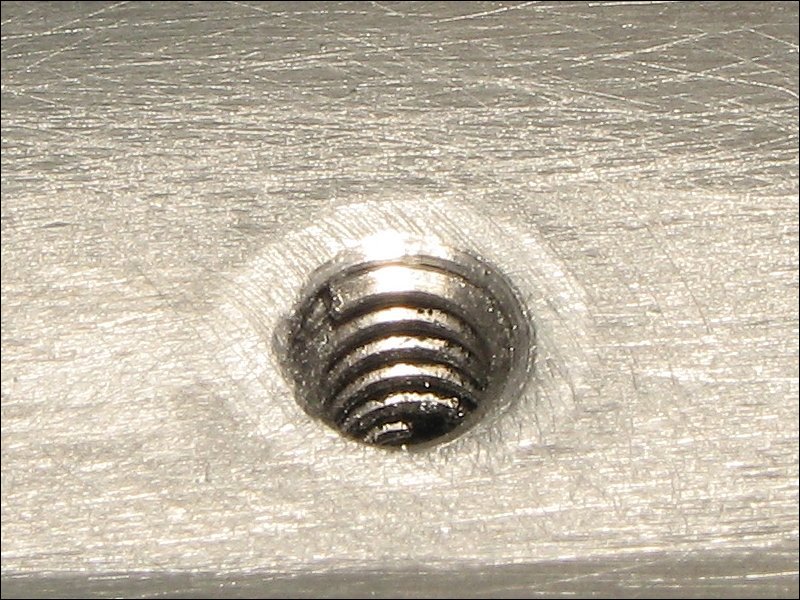
If there are a few good threads at the bottom of the hole, this is a quick, reliable fix.
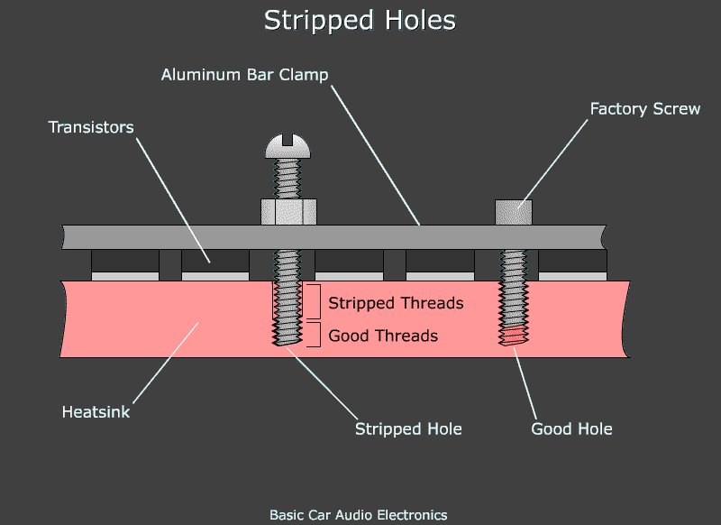
If there are no good threads or you want an absolutely reliable, permanent repair, install threaded inserts (Helicoil, Recoil...).
Is the amp louder (more gain) at low power or does this amplifier produce more output at the point where it just begins to clip?
If there are a few good threads at the bottom of the hole, this is a quick, reliable fix.
If there are no good threads or you want an absolutely reliable, permanent repair, install threaded inserts (Helicoil, Recoil...).
the fets are playing a part as well as the opamps, really...
the TI opamps are tighter... really im not imagining it.
the fets play a BIG role ,ive had irfz44, irfz48, smp60n06, in each amp and hands down the 3205 is best out of these.
faint bass notes in the background are more pronounced than before...i usually listen to the same 4 cd's every week then change when i get bored with them, so im familiar with the bass in the songs.
thats why i went ahead and did these two changes without question, so the other 3 amps are half way there.
i already tried the cap change for this amp and it lost volume, so changed them back.
------------------------------------
Perry im glad you asked when it clips...
its stronger throughout all levels, especially when it goes into clipping, it just goes crazy...when the other 3 start to level off and flatten, the loud one is like its shouting at the top of its lungs but is loud and clear, strong and hard and keeps climbing... still damped fairly well....i havent found its limit yet because my electrical goes first...50ah batt, 65 ah alt. (for now)
im pretty sure the other part is the gain, i was taking a look at the pdf's for the current gain of the MPSU vs BD909/910 vs 2n6488/91...take a look if you have a chance, i dont know if im reading it right.
the gain is only a little bit above half way... the others were at 80%.
in another post i tried two amps at 8 ohms...this one amp alone at 4 ohms is way louder....it really is louder, maybe not more powerful...but louder.
really, no BS...im not kidding
the only other things ive changed are the pots, 25v tantulums and the 4 big grey 6 ohm resistors to 5watt 5.6 ohms...
i need to check the pot one more time to see if it is a fast rate or a slow rate pot..and also which location i put them in, do to stem length.
( i didnt know rates existed until the salesman told me, i thought a 50k pot was a 50k pot)...this pot wasnt changed at the same time.
oh...and im not getting disallussioned by the deck volume.
---------------------------------------------
for the stripped holes i used some screws with a wider pitch and thread locked them into place for right now...almost all of them were stripped or were on the verge of being stripped.
i used cut strips of kapton on the securing rails..i will never use double sided tape again !
You need to switch off the bass boost/eq and match the gain on all of the amps. The best point to do this at the preamp level is the left-most leg of the muting transistors. You can also match them at the speaker outputs. The results will be the same.
Use a test tone of 50-100Hz. Black meter lead on the RCA shield. Set them as close as possible and don't touch the gains for the remainder of testing. Leave the EQ off also.
When testing, you need to measure both the AC output and the rail voltage at the onset of clipping. You would need to use a sine wave to be able to measure the AC voltage at the output. I'm assuming that you don't have a scope.
The DC current gain of the transistors has absolutely nothing to do with the gain of the circuit. Unless the replacements were defective, the difference in current gain won't be a problem.
You should install the inserts in all of your amps. I'm sure that most of them have at least one stripped hole. It will probably take about 3-4 hours for the first amp and about 1.5 hours for each of the others. It takes a bit of practice to be able to install the inserts quickly. A drill press makes the task much easier.
the bass boost on the amp stays off (on all amps), i never turn it on....when using this amp i have to turn off the boost on the Phoenix Gold MX-2 crossover also, as well as my bass cube.
when using the other amps i have to turn on atleast one, but never the one on the loud amp.
right now i only have one amp installed at a time, been swapping them out all week... to test after changing the parts...
are the test tones on your cd sinewaves? i dug it up this morning but have to wipe off the laser on my cd player, it has problems reading cd-r's when it gets glazed.
----------------------------------------
should i measure output power while the amp is connected to the subs (box rise)? or find a big resistor? ok to use a lone voice coil?
When testing, you need to measure both the AC output and the rail voltage at the onset of clipping
does this mean when it starts to clip, or right before it starts.
how many do you want me to test? since the fets and opamps have been changed on all amps already...
isnt it possible for the amps to have the same power output, but sound differently?
this amp does not sound the same, the head of the bass is fuller and has more impact.
The test tones are on the CD.
You need to test the amp that's louder and at least one of the others.
You need to use precisely the same load for each amp.
You need to measure the voltages at the output level where you can just begin to hear clipping. Drive each amp to the same amount of clipping (where it's just barely audible) and take the measurements.
Before the onset of clipping, if two amps are producing the same power with a sine wave, they should sound precisely the same unless one is defective.
i over looked three parts, i had replaced the vertical regulator, transistor and that big resistor next to them in the power supply...
are these part of the pulse voltage modulation circuit? maybe the other 3 arent performing as they should?
i'll have to test in the morning, i have to borrow my friends DMM, i have a fluke and a clamp...i want to measure the current also.
are these part of the pulse voltage modulation circuit? maybe the other 3 arent performing as they should?
i'll have to test in the morning, i have to borrow my friends DMM, i have a fluke and a clamp...i want to measure the current also.
- Status
- This old topic is closed. If you want to reopen this topic, contact a moderator using the "Report Post" button.
- Home
- General Interest
- Car Audio
- 4 amps 3 subs