Thanks by comments
Hello SMPS builders
I'm your fan, because I learn so much with all you. Than you very much.
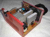
The battery charger/power supply don't have a current limiter, only a input fuse to prevent overload or short circuit, ok?
The PWM card work with SG3524, 2SC954/2SA733 buffers, IRFP264 mosfets in the output and the output transformer was build with 3 PC power supply output transformer (together) Ae = 3,6cm2 and no load the input current is only 0,04A (40mA).
I will post some schematics in the future for you.
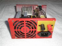
Here a pic of the SMPS rear side.
Thanks
CHACALPOWERS
Hello SMPS builders
I'm your fan, because I learn so much with all you. Than you very much.
The battery charger/power supply don't have a current limiter, only a input fuse to prevent overload or short circuit, ok?
The PWM card work with SG3524, 2SC954/2SA733 buffers, IRFP264 mosfets in the output and the output transformer was build with 3 PC power supply output transformer (together) Ae = 3,6cm2 and no load the input current is only 0,04A (40mA).
I will post some schematics in the future for you.
Here a pic of the SMPS rear side.
Thanks
CHACALPOWERS
Attachments
cores & current limit
HI luka
Yes, 3 PC power supply cores for 30A version only.
Hi Eva, I'm your fan, ok?
When I built the SMPS my time very short, but I want install a current limiter shutdown based in the next version. About this, what the best way to action the shutdown in the SG3524 (your suggestion)?
Thanks
Chacalpowers
Method 1:
Replace SG3524 by SG3525A and use the shutdown pin to terminate each cycle in case current rises above a certain threshold. This requires some "slope compensation" for stable operation into limiting.
Method 2:
Use a shunt to sense output current and one or two op-amps with suitable frequency compensation to reduce target output voltage or duty cycle in order to keep current below the limit.
And so...

Eva said:Method 1:
Replace SG3524 by SG3525A and use the shutdown pin to terminate each cycle in case current rises above a certain threshold. This requires some "slope compensation" for stable operation into limiting.
Method 2:
Use a shunt to sense output current and one or two op-amps with suitable frequency compensation to reduce target output voltage or duty cycle in order to keep current below the limit.
And so...
Eva, won't pulse-by-pulse current limiting tend to reinforce any imbalance on the balancing capacitor? The half period with the lower transformer voltage gets longer conduction time, decreasing its voltage even more for the next cycle and so on.
(http://www.fairchildsemi.com/an/AN/AN-7531.pdf)
current limiter and others
Hi
In the Rod Elliott page there is a good SWITCHMODE PSU PROTECTION
http://sound.westhost.com/project108.htm
I think build this, any other idea or schematics?
Regards
CHACALPOWERS
Hi
In the Rod Elliott page there is a good SWITCHMODE PSU PROTECTION
http://sound.westhost.com/project108.htm
I think build this, any other idea or schematics?
Regards
CHACALPOWERS
Excuse me
Hi luka
Excuse me AND MY BAD ENGLISH . I lost the page. Here it's. I understand your explanation.
http://ludens.cl/Electron/PS40/PS40.html
Thanks
CHACALPOWERS
Hi luka
Excuse me AND MY BAD ENGLISH . I lost the page. Here it's. I understand your explanation.
http://ludens.cl/Electron/PS40/PS40.html
Thanks
CHACALPOWERS
Re: current limiter and others
A simple panel mount circuit breaker? drill a hole and attach two wires. It's a great 'afterthought' type of solution.
- Matt
CHACALPOWERS said:Hi
In the Rod Elliott page there is a good SWITCHMODE PSU PROTECTION
http://sound.westhost.com/project108.htm
I think build this, any other idea or schematics?
Regards
CHACALPOWERS
A simple panel mount circuit breaker? drill a hole and attach two wires. It's a great 'afterthought' type of solution.
- Matt
- Status
- This old topic is closed. If you want to reopen this topic, contact a moderator using the "Report Post" button.
- Home
- General Interest
- Car Audio
- Smps Car Battery Charger