Hello, I had posted earlier about a Memphis 16-ST1500D With some bulging output capacitors.
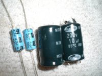
The specs are 200 volt 10uf Non-Polarized (Samwha BP M7A) Anyway I can not find replacements anywhere. Perry gave me a model number through JBL, But they are out and could be months before they are in stock. So I ordered some non-polar 100volt 4.7uf's {The only thing I could find at Mouser} And was going to parallel them together, But the problem is even together they are only half the physical size of the bad one. Is this going to hurt the sound quality? I know it's just a sub amp but I don't want to lower the SQ in any way. And I am replacing 4 caps all together along with 8 IRF3205's. I've uploaded a picture of the old cap's next to the replacement cap's. Thanks.
Please let me know if anybody knows where I can find these cap's. I have tried Dogpile & Google search and Mouser, Digi-key, All Parts, and 7 or 8 other supply houses.
Attachments
Those are only 100 volt caps. What's the rail voltage in the amp?
If the rail voltage is less than 100v, the caps may hold up. When testing, you need to drive the amp hard (into clipping on peaks) into its lowest rated load while monitoring the temperature of the caps. If the caps become uncomfortable to touch, they probably won't hold up. The amp should be driven like this for at least 30 minutes.
When testing have the bass boost at the minimum setting and the crossover set to the highest frequency. Test with music that has a wide range of low frequencies.
You should wear eye protection. If the capacitors are not up to the task, they could explode.
If they hold up and have the same capacitance as the originals, there should be no degradation of sound quality.
Parts Express has bipolar caps in 10uF, 100V ratings. $0.55 each.
Most likely, as Perry has indicated, the 100V caps will be fine. However, the half sized capacitor will potentially cause an early rolloff of the low frequencies. You'd have to know a little more of the design to know for sure. Might not make any difference.
The other possibility is to series two 22uF, 100V capacitors together. End result is a 11uF, 200V bipolar cap. Advantage here is you can get away with using polarized caps, which are typically smaller in size. Difficulty is getting it all to fit on the circuit board.
Itsme said:Hello, I had posted earlier about a Memphis 16-ST1500D With some bulging output capacitors.
The specs are 200 volt 10uf Non-Polarized (Samwha BP M7A) Anyway I can not find replacements anywhere. Perry gave me a model number through JBL, But they are out and could be months before they are in stock. So I ordered some non-polar 100volt 4.7uf's {The only thing I could find at Mouser} And was going to parallel them together, But the problem is even together they are only half the physical size of the bad one. Is this going to hurt the sound quality? I know it's just a sub amp but I don't want to lower the SQ in any way. And I am replacing 4 caps all together along with 8 IRF3205's. I've uploaded a picture of the old cap's next to the replacement cap's. Thanks.
Assuming these caps are on the output stage
P=V^2/R
1500Wrms at 2 ohm is 54.77V rms
peak voltage is 1.414 times rms =77.45V peak. If its in a zobel then the series R will also disipate some of the energy. Those caps should work while you wait for the correct ones to come in.
Perry Babin said:It only doubles the capacitance, not the voltage.
To double the voltage, you have to connect two in series. When you connect them in series, you double the voltage but the capacitance is cut in half (as was previously stated).
That's right, I don't know what I was thinking.
Hello, again!
I finally put some Sprague 100v 20uf's in series and fired up the amp and I get a clicking noise from the tl494cn card and the protection light flickers on and off. Also my IRF3205's are heating up. So I checked voltage on the tl494cn pins and this is what I have.
Pins:
1: 0
2: 4.9
3: 0
4: 3.6
5: 1.4
6: 3.6
7: 0
8: 11.9
9: 0
10: 0
11: 11.9
12: 11.8
13: 4.9
14:4.9
15: 4.9
16: 0
No Negative Voltage.
Not sure were to go from here?
If the 3205s are getting hot with the voltages you posted, you likely have defective gate resistors or defective PNP driver transistors.
If the voltage is different when you first power up the amplifier, the audio section of the amplifier may be drawing excessive current and that's what's causing the 3205s to overheat.
The voltage on pin 4 is forcing the 494 to shut down.
When you first try to power it up, is there any DC on the speaker output? Since it has a relay, you'll have to touch your multimeter probes to the windings of the inductor near the relay. There are two windings. One meter probe will go on one color winding. The other meter probe will go on the other color winding.
Are the audio driver boards in sockets or soldered directly into the board? If they are in sockets, pull them to see if the amp will power up normally (no protection, no heating of the FETs...).
Perry Babin said:If the 3205s are getting hot with the voltages you posted, you likely have defective gate resistors or defective PNP driver transistors.
If the voltage is different when you first power up the amplifier, the audio section of the amplifier may be drawing excessive current and that's what's causing the 3205s to overheat.
The voltage on pin 4 is forcing the 494 to shut down.
When you first try to power it up, is there any DC on the speaker output? Since it has a relay, you'll have to touch your multimeter probes to the windings of the inductor near the relay. There are two windings. One meter probe will go on one color winding. The other meter probe will go on the other color winding.
Are the audio driver boards in sockets or soldered directly into the board? If they are in sockets, pull them to see if the amp will power up normally (no protection, no heating of the FETs...).
No DC at speaker inductors and yes the driver boards are soldered in unfortunetly.
The driver boards are next to the board with the B-52 and F-16 chips right?
Generally, both 1266s fail. Did you replace both of them?
The driver boards are next to the audio PWM board. They generally have white heatsink compound on the driver transistors.
Pull the rectifiers to see if you can get the amp to power up.
Do the power supply FETs get hot without the rectifiers in the circuit?
Did you pull the power supply driver board when you replaced the 1266?
Perry Babin said:Generally, both 1266s fail. Did you replace both of them?
The driver boards are next to the audio PWM board. They generally have white heatsink compound on the driver transistors.
Pull the rectifiers to see if you can get the amp to power up.
Do the power supply FETs get hot without the rectifiers in the circuit?
Did you pull the power supply driver board when you replaced the 1266?
Yea I did pull the power supply driver board to replace the bottom 1266, (Only replaced one of them) It was at the bottom of the board where I couldn't get to it.
Are the rectifiers the kia7812a's (2) or the c25m's (3) and MUR3040PT (1)?
Perry Babin said:C25m and 3040
Did you damage any vias when you pulled the driver board?
Nope, I wicked out the solder real good and it came out fairly easy. No damage.
- Status
- This old topic is closed. If you want to reopen this topic, contact a moderator using the "Report Post" button.
- Home
- General Interest
- Car Audio
- Capacitor problems