I just replaced the outputs in one channel of this amp and i'm happy to say that the channel now works.However now that this channel is working I believe i'm having some issues with an op amp or possibly the input mode switch.When the amp is switched into the 1+2 input mode or mono input mode both channels have equal output but when switched into the stereo input mode position I'm only getting output on one channel but the output is equal to the sum of both channels as if the amp was bridging itself into only the right channel.I'm thinking this is possibly what lead to the blown channel in the first place as it seems the amp is trying to push all its power out of two transistors instead of four.I also noticed that when the amp is in the stereo input mode it takes a little more gain on channels 1-2 to equal the output of channels 3-4.
i haven't got the amp torn back apart yet.The rcas appear to be fine.I jiggled them a bit and got no change in output . I hope it isn't an opamp as the ones in the amp appear to be hard to find.KIA6295S I believe is the part number. I haven't found any of those yet.I'm searching for an equivalent just in case that turns out to be the problem.
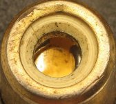
You can't go by the way the connections look on the board. Desolder the connections (add new solder, desolder and resolder). If one of the posts is broken (a common problem on some jacks), it will be obvious when you heat the connection.
If the solder connections aren't the problem, the contacts are probably loose inside the jack. These jacks use wire to contact the center conductor of the RCA plug. The wire is wrapped around the center of the connector. You need to bend the wire inward (towards the center of the hole) where it turns 90°. If you bend the free end inward, it may get pushed back into the center and cause problems. This is easier to do with the jacks off of the board.
If the solder connections aren't the problem, the contacts are probably loose inside the jack. These jacks use wire to contact the center conductor of the RCA plug. The wire is wrapped around the center of the connector. You need to bend the wire inward (towards the center of the hole) where it turns 90°. If you bend the free end inward, it may get pushed back into the center and cause problems. This is easier to do with the jacks off of the board.
Attachments
the connectors on the inside were a little loose but ultimately it turned out to be a broken solder joint.It looked good but the second I unsoldered a few of the other connections this one just pretty much fell through the board.Thanks for your help Perry. Another valuable lesson learned.
- Status
- This old topic is closed. If you want to reopen this topic, contact a moderator using the "Report Post" button.
- Home
- General Interest
- Car Audio
- Alpine MRV-F400 op amp problems?