Trying to fix a sony xm2002gtr, a 2ch or 500wrmsx1 auto amp made in '06. I found a shorted power mosfet on each bank of 3 that blew a trace. After some searching found a replacement for the sanken $15 sony part and installed all 6 for 15, as you can buy this amp for roughly $100+ship. Looked very close but new ones a little faster timing, can post if needed. Resistors looked good, tested all good, solder looked good. Started on limited power, eventually ran it on a car HU and to 8ohm house speakers and it played fine at low volumes I ran. Then I noticed one channel of the outputs was getting warm so I killed everything.
I tested all of the outputs for shorts and the resistors...everything looks ok. Don't have a manual for it yet but it has bias pots it looks like, they do affect voltage to speaker leads. I turned that one down and it still has more voltage (2.6 think it was, compared to 1.8 on other channel and .8 on other leads). Nothing is grounding to the heatsinks, no other visible damage I can find. Rails show + and - 48v, only thing I found is near a surface mount in the OP amp there was a black ink looking spot. Could be ink or something puked a little not sure. Black one with three leads. Ran the amp again for a while with no load or input, the one channel gets maybe 100F on the 1" block of aluminum the chips are mounted to. That block mounts to case for more heat transfer when assembled. Can't really tell by feel if one or more chips do/don't get hot or all, it is warm to hand but can keep hand on no problem.
Not really sure what to look at now, everything else in amp and power supply is cold and it plays music. At this point my direction is getting fuzzy so I thought I would ask for some suggestions. Here is a pic of amp, surface mounts are on back side mostly. Two power fets that were blown are marked, the sink at other end is the warm one.
An externally hosted image should be here but it was not working when we last tested it.
If the bias control won't reduce the current to a level that allows the outputs to run cool, you either have a drive problem or a leaking output.
The bias controls shouldn't have an effect on the DC offset on the speaker terminals. Were you measuring the voltage across the speaker terminals or did you use the chassis ground as the reference?
The bias controls shouldn't have an effect on the DC offset on the speaker terminals. Were you measuring the voltage across the speaker terminals or did you use the chassis ground as the reference?
That was to ground for whole amp, just wanted to see if they were the same or close. I did lead to lead but don't remember exactly what it was. Also that was the leads from the outputs, one side is reversed for bridging I believe so the output is the negative there. Right, the pot lowers voltage to a point and no more, and it is still higher on that channel.
I also get higher voltage (about same, 1/3 more) at the pot for that channel but let me double check that if important. My next tentative step was to pull the outputs one by one, can't really test for leaks can you? Looked at the surface mount stuff for a while and can't find any visible clues in the driver/output areas. Checked the drivers for shorts but figure they would not play music if they were.
I got it broke, have no idea what happened to it but it looks fairly nice.
If you haven't yet pulled the output transistors, measure the DC voltage from pin 1 to pin 3 on all 6 outputs of the defective channel.
Each one of the 3 in parallel should read the same but you need to check all of them to confirm this.
If the voltage is the same for each transistor in each group of 3 parallel transistors, post the voltage for the N-channel group and for the P-channel group. If you have one that's not the same as the others, also post its voltage and circuit board dseignation (Qxxx).
Measure the DC voltage across the speaker terminals again.
All three were the same for both sets. Rails were at 43.4v on charged but weak battery no load or input. 3 on N side had 3.6v, P side had 3.3v. Two outside pins.
Checked speaker terminals to each other with meter at 200Mv and for + to - hot side showed 2.5 and good side was 1.4. + to + was 1.1 and - to - was 0. That was treating the outputs as + even though one is reversed, the good one is.
BTW, thanks for the help and what a great site you have
Checked speaker terminals to each other with meter at 200Mv and for + to - hot side showed 2.5 and good side was 1.4. + to + was 1.1 and - to - was 0. That was treating the outputs as + even though one is reversed, the good one is.
BTW, thanks for the help and what a great site you have
It looks like the outputs are probably OK and simply biased too high. If you get run out of things to check, you could pull them and check them but I don't think you'll find that any are defective.
If the bias pot can't get the bias current down to an acceptable level, look at the solder connections on the bias transistor and the surface mount resistors in the area of the outputs and the bias pot. You may need to use a high power, lighted magnifying glass to see any defects. Desolder (very important) and resolder any suspect solder joints.
If you don't have an amp meter on your power supply, you can monitor the bias current by measuring the DC voltage across the emitter (source) resistors (the large white resistors). Low voltage means low current. Use the voltage across the source resistors of the good channel as a reference.
If you measured 200mv DC across the outputs, the amplifier may have other problems. 200mv isn't likely to damage any but the most fragile speakers but it's excessive by most standards.
Yes I was thinking of a magnifying lamp on an arm.
The meter was at 200mv setting, for some reason it has 200 and 2000 as lowest settings instead of 10 base? So I guess those readings would be in mv. The speaker leads show 0 at 200v setting I checked the transistors with, the regular volts reading.
The meter was at 200mv setting, for some reason it has 200 and 2000 as lowest settings instead of 10 base? So I guess those readings would be in mv. The speaker leads show 0 at 200v setting I checked the transistors with, the regular volts reading.
So it should be 2.5mv and 1.4mv at the speaker terminals. I have good light and a big 4" mag glass, but those things are tiny what a pain. I will check best I can next pass at it.
The one with the spot next to it might be suspect, its in that area. It may be a transistor with the three leads but I can't see a number on it. I will test it and see if the other channel has the same, once I trace it more and see where it divides on the board better.
The one with the spot next to it might be suspect, its in that area. It may be a transistor with the three leads but I can't see a number on it. I will test it and see if the other channel has the same, once I trace it more and see where it divides on the board better.
If you suspect that you have a defective transistor, that's where you should begin. It should be marked but will probably have only 2-3 letters/numbers on it. You'd need to look up the actual part number. Google 'smd codebook'. If there are several different part numbers for the code on the transistor and the case styles are very similar, you'll have to carefully measure the transistor with dial calipers to determine which transistor you have.
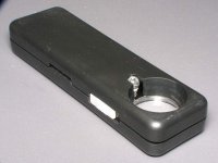
Most of the lighted magnifying glasses on an arm are useless for this type of work. The distortion and chromatic aberration are so bad that you can't see much more than you can with the naked eye. If you intend to continue doing this type of work, buy a lighted magnifier like the one in the attached image. I've tried many different lighted magnifiers and these are the best I've found. They are rated at 10x mag.
Most of the lighted magnifying glasses on an arm are useless for this type of work. The distortion and chromatic aberration are so bad that you can't see much more than you can with the naked eye. If you intend to continue doing this type of work, buy a lighted magnifier like the one in the attached image. I've tried many different lighted magnifiers and these are the best I've found. They are rated at 10x mag.
Attachments
Perry,
where would one find that specific 10x magnifier in the picture? do you happen to know the maker or part number? i was thinking of getting a cheap lighted one on an arm but since you say these are better i'm willing to save some bench space and give this small one a shot.
where would one find that specific 10x magnifier in the picture? do you happen to know the maker or part number? i was thinking of getting a cheap lighted one on an arm but since you say these are better i'm willing to save some bench space and give this small one a shot.
Go to eBay and search for:
10x lighted magnifier
For inspecting solder connections on SMD components and reading the numbers or color codes on resistors (particularly the 1% resistors with the dark blue bodies), these work very well. For viewing anything larger than ~1/2", you'll need something else.
10x lighted magnifier
For inspecting solder connections on SMD components and reading the numbers or color codes on resistors (particularly the 1% resistors with the dark blue bodies), these work very well. For viewing anything larger than ~1/2", you'll need something else.
I looked at it for a while and have not found anything yet. I did find a SMD resistor that was replaced way over by the power section, right under the large transformer you can see the solders for. Thinking I will have to test and try to trace back voltage differences, maybe check some things first.
I took a cruddy pic of things. The "spot" SMD says ALY on it, then sideways 03. Very hard to see, that magnifier looks like a great idea! Hope nobody has a dialup...this pic is the board:
Here is half with hot sink at left, pot for it highlighted, upper right is a box with the spot in it near RCAs.
And this is close up of spot. It was covering the solder too until I hit it with my tester. It could just be ink, it is that deep purple color.
I took a cruddy pic of things. The "spot" SMD says ALY on it, then sideways 03. Very hard to see, that magnifier looks like a great idea! Hope nobody has a dialup...this pic is the board:
An externally hosted image should be here but it was not working when we last tested it.
Here is half with hot sink at left, pot for it highlighted, upper right is a box with the spot in it near RCAs.
An externally hosted image should be here but it was not working when we last tested it.
And this is close up of spot. It was covering the solder too until I hit it with my tester. It could just be ink, it is that deep purple color.
An externally hosted image should be here but it was not working when we last tested it.
I got some batteries for a better tester I have, a BK Precision. Should be easier to test stuff, I guess I'll start checking things on the board. I found two resistors replaced under the coil there, or at least the solder is not shiny like the rest but they did a good job. I don't yet know what that little section of components is for, unless it's some kind of mod but seems unlikely with this type of amp. Naturally I'd hoped the mosfets would have fixed it but I guess not. Also don't have a scope to set the bias if I do figure it out.
You don't need a scope to set the biasing. You use the voltage drop across the large white source resistors. Each resistor has two resistive elements. The center leg is common. To determine if the current flow is equal in all of the transistors, you need to measure the voltage across each of the 6 resistors for the channel.
On the good channel, what's the lowest voltage you can get across the source resistors with the pot set at the lowest bias level?
What's the lowest you can get on the channel that's overheating?
You'll have to set you meter to the lowest range if it's not auto-ranging. The voltage will be well under 1 volt.
I will check it out. Did test the resistors across and they were all the same ohms if that matters (end to end), I see they have three legs. This meter is auto, much better than the clark I was using. Had to find those little 44 batteries.
Once fixed I could try to match it with the good channel since it should not have been moved, but I don't know the proper setting via meter unless I buy the manual...might have to. And here I just bought another amp cheap that has damage...
Once fixed I could try to match it with the good channel since it should not have been moved, but I don't know the proper setting via meter unless I buy the manual...might have to. And here I just bought another amp cheap that has damage...
Ok, I checked and the hot side was from 6.5-9mv and the cool side 3-5mv. Re-reading the post I let it cool a minute (not that warm) and set both bias all the way down...and they are all 0mv and it does not get hot The rails were at 48v +/-. I then checked the gate voltage (to chassis -) and the P were 2.7 and N was 2.25 on both channels, all very close to those numbers.
When I had moved the hot side bias down before, I was looking at speaker terminal voltage and the block takes a little to warm/cool.
Did I assume nobody had touched the gain pots or might there still be an issue? Both pots were near the same place, but they are not the same now full minimum. Do I set bias and try it...but don't know what to set it at since what I thought was the good channel may have been fiddled with too, if that is all that was/is wrong.
The rails were at 48v +/-. I then checked the gate voltage (to chassis -) and the P were 2.7 and N was 2.25 on both channels, all very close to those numbers.When I had moved the hot side bias down before, I was looking at speaker terminal voltage and the block takes a little to warm/cool.
Did I assume nobody had touched the gain pots or might there still be an issue? Both pots were near the same place, but they are not the same now full minimum. Do I set bias and try it...but don't know what to set it at since what I thought was the good channel may have been fiddled with too, if that is all that was/is wrong.
Slowly increase the bias while watching the voltage across any one of the source resistors. Increase the biasing until the voltage is ~0.001 volts across the resistor. After checking one, check the rest to confirm that they're all the same (or close) for that channel.
Do the same for the other channel.
The amp will run cool at idle set this way. This should be enough bias current to eliminate crossover/notch distortion.
Do the same for the other channel.
The amp will run cool at idle set this way. This should be enough bias current to eliminate crossover/notch distortion.
Thanks again, I will try that out next session and let everyone know what it does. If it works, well I never said I was very good at this...but that is how you learn.
I could use this for a sub amp, but actually am trying to get a class D that has less power draw. It would need obvious distortion to notice on subs.
I could use this for a sub amp, but actually am trying to get a class D that has less power draw. It would need obvious distortion to notice on subs.
- Status
- This old topic is closed. If you want to reopen this topic, contact a moderator using the "Report Post" button.
- Home
- General Interest
- Car Audio
- fixed amp, get heat in one channel