Have a problem with my newest investment ")
I bought a Infinity 202a amp from internet.
I opened it up and saw that the big electrolyts was
a bit swollen on top so i replaced them.
I powerd the amp upp and noticed that the last pair
of output FETs got quite hot after just a few seconds
so i disconnected. (the pair to the very left on pic.)
None of the other FETs was not even near hot.
Something must be wrong here? What should i look for.
I also noticed that someone has marked one of the smaller
i think power supply fets with black and a mark on the side.
(the one to the very left on the pic.)
What does this usualy means?
Attachments
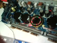
If you're talking about the white square things, those are resistors. The fets are under the long metal bars, strapped to the heatsink. I've seen many amps with marks like that, I think the people that build them do that for some reason. You'll probably need to test the power supply transistors and output transistors, using a volt/ohm meter. There are a few people who can make suggestions on the best way to do it.
At the lower left edge of the board one can also see power transistors. Are you talking about those ?
Did you test without heatsink - like shown on the photograph ? If yes, then sometransistors may for sure get hot even under normal conditions. I wouldn't run the amp like that !
Regards
Charles
Did you test without heatsink - like shown on the photograph ? If yes, then sometransistors may for sure get hot even under normal conditions. I wouldn't run the amp like that !
Regards
Charles
If only two of the 4 FETs for that channel are getting hot, the first thing I would do is to pull all 4 of them and check them out of the board.
If none are defective, power up the amp and measure the DC voltage on the gate pads of the FETs that you removed. The voltage should be ~1/2 of B+ and the same voltage for all 4 gates.
If/when you get the amp working, you're going to need to replace the insulators. You'll need to clean all of the transistors and the sink. 100% of the old insulator material must be removed. This is very time consuming but must be done if the amp is to be reliable. The easiest replacement insulator I've found is Kapton tape or Kapton insulating film.
Okay yes i know that the white "squares" are resistors
Im talking about the capacitor thats marked with a pen
on the top, just below the white square thats also marked.
And you are right it must be the power supply transistors
that gets hot and not the outputs. Its the lower transistors
to the very left. The pair of them gets hot.
And yes i know that i cant runt the amp without the heatsinks.
Just did it for testing to se if anything got abnormal hot,
and it did so i shut it down.
The power supply transistors should heat upp quite
equal or am i completly lost?
Perry its á matter of "when" haha, took me 2 weeks to finish
my last project, my alpine mrv-1505. Thanks for all the help!
I will remove them and check them out of the board.
By the way how do you know that it should be around half
the "battery" voltage on these? is it similar to all amps?
Just want to learn something =)
Im talking about the capacitor thats marked with a pen
on the top, just below the white square thats also marked.
And you are right it must be the power supply transistors
that gets hot and not the outputs. Its the lower transistors
to the very left. The pair of them gets hot.
And yes i know that i cant runt the amp without the heatsinks.
Just did it for testing to se if anything got abnormal hot,
and it did so i shut it down.
The power supply transistors should heat upp quite
equal or am i completly lost?
Perry its á matter of "when"
haha, took me 2 weeks to finishmy last project, my alpine mrv-1505. Thanks for all the help!
I will remove them and check them out of the board.
By the way how do you know that it should be around half
the "battery" voltage on these? is it similar to all amps?
Just want to learn something =)
The power supply FETs should operate at the same temperature as the others in that power supply. Typically, power supply FETs run cool at idle (no load on amp). If they do run slightly warm, all should have had the same rise in temperature.
For virtually all amps, the duty cycle will go to ~50% when the FETs have been removed. Most meters will see this 50% duty cycle square wave as 1/2 of the peak voltage. The peak voltage depends on several things but it's generally equal to (or slightly less than) B+ voltage. This means you'll read ~1/2 of B+. If one bank of FETs has ~6v and the other bank has significanly more or less (near B+ or near ground), you know that the side that's not near 1/2 of B+ has a problem.
This only works reliably when the FETs have been removed. For amps with regulated power supplies, the duty cycle will be reduced as the target voltage is reached and the DC readings on the gates may be very low.
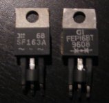
Tonight i desolder two of what i taught was the power supply
transistors. But in fact it was the rectifyer, correct me if
im wrong. The power supplu transistors are placed in the same
row and i 3 pairs of totaly 6 transistors.
And it was the rectifyer that got so damn hot i noticed.
You can se it on the picture below. I measured it.
From center to pin 1 no connection.
From center to pin 3 - 2Mohm, this must be bad!?
From pin 1 to center 253 ohms.
From pin 3 to center 37Kohm.
What could cause the rectifyer to crash?
Maybe this caused the swollen electrolyts that i replaced?
Attachments
silversweden said:Ok can i measure it the same way as i did with the other one?
It doesnt have any schematic symbol that shows how its connected internally.
The waves on the two outer legs stand for the AC "input", the - on the middle leg stands for negative "output" Either its just a different brand infinity decided to use, or maybe the amp has been repaired before.
There's something wrong with the readings you have.
When using the ohms function of the meter, you can't touch the metal part of the meter leads or the leads of the device. If you do, you will not get accurate readings.
Does your meter have a diode check function?
Page 97 of my car audio site shows how to check the rectifiers. Find the section labeled "Checking Dual Diodes".
ok it reads 4.3 and 5.4Mohms from center (red wire)
to pin 1 and pin 3 (black wire)
It should be no connection in this direction isnt that right?
But if i switch the (what do you call it? probes?)
there is no connection what so ever.
So this rectifier is also faulty, what caused them
to die? if i just replace them the new ones
maybe go the same way?
to pin 1 and pin 3 (black wire)
It should be no connection in this direction isnt that right?
But if i switch the (what do you call it? probes?)
there is no connection what so ever.
So this rectifier is also faulty, what caused them
to die? if i just replace them the new ones
maybe go the same way?
It's not supposed to show a direct connection when you use the meter in "ohm" or resistance mode. That is why there is a diode check. If they measured ok, you can check the output transistors while they are still in the circuit. Check between legs 2 and 3 on every output transistor that is clamped to the heatsink. Use the leads of the meter both ways, but just measure leads 2 and 3 for now. If you find any that measure between .3 and 10 ohms, for example, they will be toast. First find the ones that read the lowest. Post them here after checking
I believed something was wrong with the readings because they were inconsistent.
For a good diode, you should read infinite resistance one direction and with the leads reversed, I'd expect a reading between 1M and 4M ohms.
For a defective diode that read 253 ohms in one direction, I'd expect to see the same 253 ohms in the other direction.
What was wrong with the amp originally (before you replaced the capacitors)?
Does anything else get warm or hot when you power up the amp?
Ok i understand what you mean perry, with the
diod check both of them were ok, so i guess i have
to trust my meter
Originally i didnt know what was wrong, in fact i
taught that the amp was ok.
But i bought it from internet and the guy didnt now.
So i opened it up to take a quick look at it and
i saw that the electrolyts were a bit swollen.
Just in case i replaced them. (they were not cheap!)
But then i also noticed that what i taught was the
power supply transistor(one of them) got hot after just
a few seconds.
So i took a closer look at it yeasterday and it turned
out to be one of the rectifier, the other (negative)
rectifier was not hot, cant recall it..
I think this was a quite breif explanation of my progress =)
- Status
- This old topic is closed. If you want to reopen this topic, contact a moderator using the "Report Post" button.
- Home
- General Interest
- Car Audio
- Amp trouble - infinity Kappa 202a