Sometimes, the plastic cover will be raised in the center but it's not because the cap swollen. Before you replace the cap, push down on the plastic cap. If you can push it flat, the cap isn't swollen.
Are you 100% sure you installed the capacitors correctly? If you installed one backwards, it would cause the symptoms you described.
How much current is it drawing when the amp is on?
You need to measure the voltage across the emitter resistors for the right channel (the channel supplied power via the overheating rectifiers). R16A-R21A are for the R channel.
Hi perry, yes i'm 100% shure that i put the capacitors
the right way.
A funny thing is that now when i placed the rectifyers
back in circuit the amp wont power upp. But still they
get hot as hell, but why isnt anything else getting hot?
None of the power supply transistors get near warm.
Before both channels lit red for about 3 sec.
Then one channel lit green.
Now the green light doesnt happen.
I tryed to measure the amps when i powerd the
amp. But im not sure about the readings.
It showed .117 when i put my meter at 2A field
1.17 when i put it on 10A field.
Should i measure the voltage on the resistors across the legs?
Or compared to ground? Across the legs i think")
the right way.
A funny thing is that now when i placed the rectifyers
back in circuit the amp wont power upp. But still they
get hot as hell, but why isnt anything else getting hot?
None of the power supply transistors get near warm.
Before both channels lit red for about 3 sec.
Then one channel lit green.
Now the green light doesnt happen.
I tryed to measure the amps when i powerd the
amp. But im not sure about the readings.
It showed .117 when i put my meter at 2A field
1.17 when i put it on 10A field.
Should i measure the voltage on the resistors across the legs?
Or compared to ground? Across the legs i think
You said the amp isn't powering up. To confirm that it's not producing rail voltage, measure the DC voltage from the center leg of Q10 (red lead) to the center leg of Q15 (black lead). Do the same for Q10a and Q15a.
Do the rectifers get hot without remote voltage applied?
Do both of the rectifiers get hot?
Do the rectifers get hot without remote voltage applied?
Do both of the rectifiers get hot?
ppia600 i checked the output transistors as you said.
Non of them were low , think the lowest was a bit over
47k ohm. And some of them 2-3Mohm.
But for a correct reading i have to take them out of the
circuit. This just indicates me that none of them have
a direct short Dont now the use of these readings.
And still, if a output transistors is shorted i think
that the power sypply transistors would heat upp.
Why is just the rectifyers hot as hell and not the
transistors?
This is strange to me. No visible damages.
Non of them were low , think the lowest was a bit over
47k ohm. And some of them 2-3Mohm.
But for a correct reading i have to take them out of the
circuit. This just indicates me that none of them have
a direct short
Dont now the use of these readings.And still, if a output transistors is shorted i think
that the power sypply transistors would heat upp.
Why is just the rectifyers hot as hell and not the
transistors?
This is strange to me. No visible damages.
q10 - q15 reads 95volts
q10a - q15a reads 94.8volts
No the rectifyers doesnt get hot without the
remote. A funny thing is that only the positive
gets hot as hell. Cant feel that the negative
rectifyer is hot at all.
And just D3a gets hot, not D4a (as i said above).
for the other channel, D3 and D4 dont get hot.
And btw how do you know the names on the
componets?
If you have 90+ volts on the outputs, the amp is powering up.
You can measure the voltage across the emitter resistors but I doubt that you'll find any that have any significant voltage across them. If there were significant current flowing through them, the outputs would be getting hot.
At this point, I'd suggest that you pull the capacitor that's connected to the rectifier that's getting hot. It could be defective, there could be a solder bridge under it or there could be another problem.
Since the capacitors are probably difficult to get in/out of the board, you can solder a different type of capacitor (one with long leads) in its place for testing (after removing the large one). The replacement capacitor must be rated for 50v. The value isn't critical with no load.
With another capacitor in place, does the rectifier still get hot?
Hi perry! Are you talking about the biggest capacitor?
The ones i replaced?
I pulled the one thats connected to the positive
rectifyer out of the board.
I didnt find any new to test with, just have to old
ones left.
But the rectifyer get hot as hell even with the
capacitor out of the board, isnt this strange!?
The ones i replaced?
I pulled the one thats connected to the positive
rectifyer out of the board.
I didnt find any new to test with, just have to old
ones left.
But the rectifyer get hot as hell even with the
capacitor out of the board, isnt this strange!?
Yes. That's strange.
Swap D3 with D3a to see if the problem follows the rectifier that's currently getting hot or if the rectifier in the location D3a still gets hot.
There are 2 more capacitors across the positive rail (C6a and C41a). Check those to see if they're leaking (electrically).
If you've checked for solder bridges under the large capacitor that you removed, you can reinstall it.
I swapped the rectifyers and its the same one
that gets hot, it must mean that it is defective
despite the diod check that i did for a couple of
days ago. Am i right?
It should do well if i just replace one of the
rectifyer, am i right? Or could it be some other
fault as well. Something must been the cause
of this.
that gets hot, it must mean that it is defective
despite the diod check that i did for a couple of
days ago. Am i right?
It should do well if i just replace one of the
rectifyer, am i right? Or could it be some other
fault as well. Something must been the cause
of this.
Perry i have now replaced the rectifyer and it wont
get hot anymore =)
When i removed the regulator before i had to remove
a thin "sheet" that was placed over both the rectifyers.
But you said something about cleaning them.
I noticed that it was some "sand" colored thin
layer that has sticked on the regulator.
How do i remove it?
Why cant i just use the old insulator (the sheet i removed)
and just apply new thermal grease?
What is kapton tape and where do i buy it.
Just some stupid questions
Want to thank all of you for helping me!
From my experience, the insulators in these amps don't release cleanly from the sink and often leave behind some of the coating on the sink. When removed from the semiconductors, the same thing happens. This will degrade their performance. When I repair these amps, I remove all of the insulators and clean the semiconductors.
I use a razor blade to scrape the old coating from the back of the semiconductors. You have to keep a low angle so you don't dig into the component. You must keep the corners of the blade off of the back of the semiconductor (they dig in very easily).
If your insulators came out cleanly and you only need to replace the insulator on the back of the single rectifier, you don't need to do any cleaning but you will need to use an insulator that will stay in place while you slide the amplifier back into the heatsink.
Kapton (polyimide) tape is a high temp tape that can be used as an insulator. It's useful here because it has an adhesive backing and stays in place. It's relatively easy to find. Google will return lots of sources.
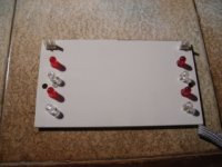
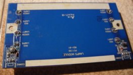
Hi again, i smoked a component on the led-board.
The two of the bulbs where broken so none of them lit.
So i replaced the broken bulbs with diods instead.
It is 4 diods in a serial circuit and i tought that i didnt need
a current limiting resistor, but i was wrong i guess.
It is 12 volts over the bulbs(wich where there before)
But i guess the diods passed to much current.
Attachments
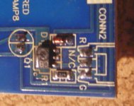
And the smoked componet looks like this.
I think its a transistor.
It is writen:
CB
M
...on it.
And it has 3 legs on one side, and 1 leg on the other side.
4 legs total
I cant figure out the function of this, and i dont
have the smallest clue on what to do.
Perry, you use to give me good help, please help =)
I think its a transistor.
It is writen:
CB
M
...on it.
And it has 3 legs on one side, and 1 leg on the other side.
4 legs total
I cant figure out the function of this, and i dont
have the smallest clue on what to do.
Perry, you use to give me good help, please help =)
Attachments
The bulbs were connected in parallel, not in series. Even with the LEDs in series, you would need a current limiting resistor.
The part number from the service manual is PXT2222a. The number for the part in the board (marked CB) is a BX68-10. Either will work but the BX68-10 is rated for more current and may have been used because the PXT2222a was failing.
If you need to look up an SMD transistor, do a google search for 'smd codebook'. Go to either of the top two pages returned and look up the code for the transistor. Since there will likely be multiple components with the same code, you need to choose the one with the correct case style.
If you're going to use LEDs, insert a current limiting resistor in the B+ wire coming from the PWM board.
The LEDs are probably blown so you should replace them or check them before replacing the transistor.
The transistor is used to switch the LEDs on.
Hi perry, cant find any datasheet on the BX68-10.
Have it on the PXT2222.
The problem is that i cant find either of the parts.
Are they usually hard to get?
Is it possible/simple to find some replacement?
And what stands the M thats written on the
component?
Thanks again!!
Have it on the PXT2222.
The problem is that i cant find either of the parts.
Are they usually hard to get?
Is it possible/simple to find some replacement?
And what stands the M thats written on the
component?
Thanks again!!
- Status
- This old topic is closed. If you want to reopen this topic, contact a moderator using the "Report Post" button.
- Home
- General Interest
- Car Audio
- Amp trouble - infinity Kappa 202a