The other day my battery died and a dumb a** jumped me and reversed the connections on accident, Anyway he got me running but now my amp doesn't power up. Completely dead. So I thourghly disassembled amp and looked for any burnt or discolored componets. None found. I don't even smell anything burnt. I am only semi circuit knowledgeable, but this amp is a little differn't then I am used to. So if anybody can tell me what to check for I would greatly appreciate your knowledge! Thank you!
Randy Here are some pic's........
Randy Here are some pic's........
Attachments
did you check the fuse/s?
often there's a large diode across the supply terminals which will cause the fuse to blow in reverse polarity. (although from looking at that pic, there isn't any diodes there)
better amps have an internal reverse-polarity sensing, and just do nothing if they're connected wrongly.
maybe also check the power and earth cables supplying the amp.
do you have 12v at the amp power cables?
a few more pics on this site:
http://www.realmofexcursion.com/ampguts/Alpine_PDX-4.150/
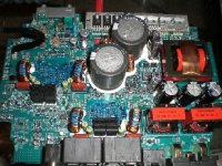
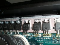
the row of transistors across the top are the SMPS switchers - maybe check none of these have shorted legs
often there's a large diode across the supply terminals which will cause the fuse to blow in reverse polarity. (although from looking at that pic, there isn't any diodes there)
better amps have an internal reverse-polarity sensing, and just do nothing if they're connected wrongly.
maybe also check the power and earth cables supplying the amp.
do you have 12v at the amp power cables?
a few more pics on this site:
http://www.realmofexcursion.com/ampguts/Alpine_PDX-4.150/
the row of transistors across the top are the SMPS switchers - maybe check none of these have shorted legs
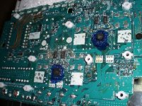
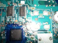
Yes I'm sorry, I forgot to mention both fuses are fine. I even tested continuity on fuses even though they were good visualy. Also yes 12.8 volts tested at inside power connectors. And it seems like the remote turn-on circuit is working. But power supply is dead. I am not getting voltage anywhere else in the circuit above 1 volt. It is a four layer PCB board and I cannot trace the 12+ circuit because it's inside the board? I think I have a picture of the protection diodes, But not sure if they are?
Attachments
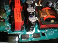
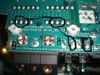
There are two large inductors near the power and ground terminals. You need to confirm that you have continuity from the fuse holders to both sides of the inductors. I doubt that they are using all of the terminals. Use your meter to see which ones are shorted togther. Those are likely to be the ones that are being used. It's possible that all of the pins of both inductors will show continuity.
From there, you should read continuity (0 ohms) to the primary side of the power transformer (the row of pins closest to the edge of the board).
From there, you should read continuity (0 ohms) to the primary side of the power transformer (the row of pins closest to the edge of the board).
This means that the connection between the fuse holders and the inductors is open. If you want to try jumping the connection, solder a wire from the fuse holder to the inductor (to the side closest to the B+ and ground terminals).
You must connect the jumper to the 'cold' side of the fuse holder. To find the cold side, remove the fuses and find the terminals that are connected to the B+ terminal. The 'other' side of the fuse holders is the cold side. Since the fuse holders may not use the same terminals for the hot/cold terminals, you need to confirm the connections for both fuse holders.
Replace the fuses and power up the amp via a 10 amp fuse (in series with the B+ power supply wire). I want you to use an external fuse in case you accidentally have a solder bridge or jump to the wrong points and defeat the fuses. If there are no other problems, the amp should power up.
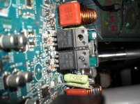
Clamp all power semiconductors to the heatsink BEFORE applying power.
You must connect the jumper to the 'cold' side of the fuse holder. To find the cold side, remove the fuses and find the terminals that are connected to the B+ terminal. The 'other' side of the fuse holders is the cold side. Since the fuse holders may not use the same terminals for the hot/cold terminals, you need to confirm the connections for both fuse holders.
Replace the fuses and power up the amp via a 10 amp fuse (in series with the B+ power supply wire). I want you to use an external fuse in case you accidentally have a solder bridge or jump to the wrong points and defeat the fuses. If there are no other problems, the amp should power up.
Clamp all power semiconductors to the heatsink BEFORE applying power.
- Status
- This old topic is closed. If you want to reopen this topic, contact a moderator using the "Report Post" button.
- Home
- General Interest
- Car Audio
- Help? Alpine PDX 4.150 Dead of reverse polarity...