hi.
I got this KAC-846 that's really messed up, so i'd like to ask your opinion on it. (i'll post some photos of it as well).
It's in a really bad shape but since i can't afford a better one, i have to fix this one. I have a few friends that will help me fixing it because i'm not that good at troubleshooting at all.
Can u help me as well, at least with some guidelines?
It cannot be powered up when connected, so i took it apart. seems some parts are missing, but i cant identify them. I'm not an expert but i see some really weird wiring inside it.
I checked that other thread from eurospanks but this amp is in worse shape than his was.
Thnx in advance.
Attachments
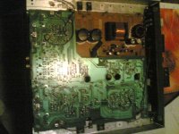
Perry Babin said:Q27-Q30 are the power supply FETs. An IRFIZ44 is a good replacement.
Thnx Perry
Can i replace all of them with this one? I mean is there any significant difference?
And what are Q20 and Q18? They are also missing.
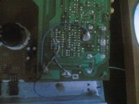
And should i remove these wires (they can be seen on this photo)
Attachments
Can i replace all of them with this one?
Those are only used to replace the power supply transistors.
Q18 = 2SC5100
Q20 = 2SA1908
I can't really see much in the photo but I don't think two of those pads were intended to be soldered to the metal tabs sticking up. and I don't think the lower right is supposed to be conected to the other two points. It appears that there is some damage near the RCA jacks. Maybe someone was trying to restore a shield ground connection but that's just a guess.
Is there anywhere i could find the service manual for this one? Should be helpful.
I tried every possible search i could think of.
I would post some better pics but i can't due to size restriction.
If u want i could send them to you via e-mail.
Thnx again for bothering with me.
I tried every possible search i could think of.
I would post some better pics but i can't due to size restriction.
If u want i could send them to you via e-mail.
Thnx again for bothering with me.
Email me the photos but before you do, remove the jumper wires and remove as much solder as possible so I can see the board. Please zip the photos into one file.
babin_perry@yahoo.com
babin_perry@yahoo.com
On the 5100...
Red lead on the first leg and black on either of the other legs should give you approximately 0.6v with your meter set to diode check. With the leads reversed, you should read infinite resistance (or open on diode check). There should be infinite resistance between legs 2 and 3.
For the other transistor swap the meter leads where they plug into the meter and perform the same tests.
- Status
- This old topic is closed. If you want to reopen this topic, contact a moderator using the "Report Post" button.
- Home
- General Interest
- Car Audio
- A problem with Kenwood KAC-846