Yes, this I do know. Read that in a couple of other repair threads. Thanks for the heads-up, though. I may end up building some sort of frame that can be screwed down independent of the bottom plate, as I've seen pictures of in some other thread on here (might've even been you that posted 'em?), but for the immediate future will at least make sure the bottom cover is nice & tight.
Once again, thanks...
Pyro
Once again, thanks...
Pyro
I'd like to see pics of the repair work. Curious as to what he did with the metal strips. He was probably just trying to make sure the transistors stayed pressed against the sink. I don't really like this system ppi used to hold them down, the bottom screws strip easily, especially after pulling the cover a few times. (But I guess if the amp is working properly there's no need for that) I actually took care of this problem with an art600 I had a few years back by drilling the holes completely through the sink. Then I made counter sunk holes in the top of the amp for the bolt heads. Next I cut the bolts to just a little shorter than the amp height and used self locking nuts on the bottom. It actually looked very nice after I removed the white powder coat (kind of scratched up) and polished the aluminum to a nice shine. ")
Sorry you've had to go through so much to enjoy the amp again. It will be worth it though, those amps are great. I've got the same amp sitting in my storage room. One of my friends is supposed to buy it, if not it will be up on ebay in a few weeks.
Sorry you've had to go through so much to enjoy the amp again. It will be worth it though, those amps are great. I've got the same amp sitting in my storage room. One of my friends is supposed to buy it, if not it will be up on ebay in a few weeks.
ppia600 said:I'd like to see pics of the repair work. Curious as to what he did with the metal strips. He was probably just trying to make sure the transistors stayed pressed against the sink.
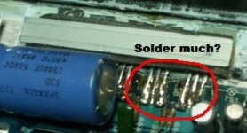
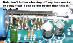
Perhaps, but on top of adhesive-backed foam strips that were stuck to the transistors?? Seems a bit counter-productive for heat dissipation to me. Plus, there was no reason to replace the screws...especially with the ones he chose to replace them with! Note the copious amounts of solder used and the poor alignment or the transistors that were replaced. I know the alignment & spacing probably makes no difference in performance, I just think it's a sloppy job. Certainly not what I would call "quality" work. Also not a huge deal that he soldered wires onto the back of the output connector, since he didn't have a PPI output plug to use to test the amp...but I was the one who had to remove these wires!! If I hadn't, whatever I couldn't have cut off from the outside would still be almost sticking out of where the connector plugs in.
If it weren't for the helpful people on this forum, I more than likely would have reinstalled my amp again, only to have it fail a third time...after which I would have had to seek out someone else here in town to try fixing it again (at additional expense) or just put it in a closet somewhere in hopes of finding a working one that I could afford on eBay.
But even after all of this, I will say that there were a few things good to come of the whole thing. I learned a little bit more about the inner workings of car amplifiers, and will soon have this puppy working like it used to once again. As juvenile as it sounds, I had forgotten how much fun it can be to drive through a parking garage or crowded parking lot with my BachBusters CD cranked and see how many cheap car alarms start goin' off!!
I know, I know...I'll grow up later, LOL!
Hope these pics are big enough to show the details I'm trying to show. Had to down-size them in order to post 'em.
Pyro
Attachments
Hmm...can't seem to post more than one attachment per post. Ok, hopefully it's not unacceptable to post them like this:
Geez...looks like only two per post.
One more post coming...
An externally hosted image should be here but it was not working when we last tested it.
An externally hosted image should be here but it was not working when we last tested it.
Geez...looks like only two per post.
One more post coming...
Attachments

Well, the closest I could come to 1/4 Watt, 100 Ohm, 5% tolerance were these two:
1/2 Watt, 100 Ohm, 5% tolerance
and
1/4 Watt, 110 Ohm, 2% tolerance

If memory serves, I'm thinking the 1/2 Watt ones would be acceptable...but wanted to ask the experts before committing to them. If these must be exactly 1/4 Watt, 100 Ohm at 5% tolerance, I guess I'll order them (I kinda would like to get some fresh mica insulation stuff as long as I have the amp all apart anyway). Digikey usually ships pretty quickly...
So would the 1/2 Watt ones make a dangerous enough difference to need to order some 1/4 Watt ones? And does anyone know if Digikey, or perhaps Moeseur (sp?) sell the mica stuff?
Thanks in advance,
Pyro
1/2 Watt, 100 Ohm, 5% tolerance
and
1/4 Watt, 110 Ohm, 2% tolerance
If memory serves, I'm thinking the 1/2 Watt ones would be acceptable...but wanted to ask the experts before committing to them. If these must be exactly 1/4 Watt, 100 Ohm at 5% tolerance, I guess I'll order them (I kinda would like to get some fresh mica insulation stuff as long as I have the amp all apart anyway). Digikey usually ships pretty quickly...
So would the 1/2 Watt ones make a dangerous enough difference to need to order some 1/4 Watt ones? And does anyone know if Digikey, or perhaps Moeseur (sp?) sell the mica stuff?
Thanks in advance,
Pyro
PyroZona:
The wattage isn't critical. The larger size won't fit into the alloted space so you'll have to stand them up.
Mouser has the insulators but not in the long strips. You'll have to buy individual TO-220 insulators.
Is one of the insulators damaged?
ppia600:
If you have another one with stripped holes, email me. You don't have to drill all of the way through to repair the sink.
Perry Babin said:PyroZona:
Mouser has the insulators but not in the long strips. You'll have to buy individual TO-220 insulators.
Is one of the insulators damaged?
Well, I'm not really sure. When I was pulling them out of the thermal grease, it seemed like there were 2 layers to one or two of the mica strips...but one of the layers of each of those was much thinner and pretty much came apart, much like celophane would if you left it out in the sun for a year or two (I guess). Also, in the spots where the transistors that grenaded themselves were, there are darkened, burnt spots that still smell like burnt electronics. I'd like to replace them all just cause I have it all apart...kinda like I would likely replace my valve cover gasket on my Jeep's engine if I had to remove the valve cover to repair something under it. I'm just a "as long as I'm doin' it..." kinda guy.

Pyro
Yeah, that does looke kind of rushed/sloppy (the pic with the cap mainly), but as long as the legs aren't touching anything they shouldn't be, and if the solder is a clean connection, it should be ok. It almost looks like he just added the metal strip and the foam to make the bottom cover press harder. He could have just bent the metal cover legs slowly back into place to make sure they are holding the transistors securely.
UPDATE:
Well, I'm VERY happy to report that changing out the resistors seems to have done the trick! YAY!! My amp now sounds much more like it used to and will only heat up to about 128 degrees F if I really push it (I now keep my little laser temp gun in the car for routine heat checks). I got some thick-wall aluminum tubing and cut 4 little 1/2" spacers to mount under the amp so that it sits up off the carpet of my box. Figured it might help to have airflow under the amp. Time will tell, I guess...
HUGE thanks to Perry for his help getting my amp going reliably again! I don't know why it kept grenading itself with the factory resistors in it, but the change-out appears to be just what it needed. I'm keeping my fingers crossed and taking it a bit easy on the low-end tune'age for a while just to make sure the new thermal grease (arctic silver...although it's not white anymore, but a dark gray color out of the tube) gets settled in correctly. I did make sure the bottom cover was applying adequate pressure on the transistors before buttoning the amp up completely, and was thankfully able to use the original allen-head screws.
Ain't the internet a wonderful thing sometimes??
Pyro
Well, I'm VERY happy to report that changing out the resistors seems to have done the trick! YAY!!
My amp now sounds much more like it used to and will only heat up to about 128 degrees F if I really push it (I now keep my little laser temp gun in the car for routine heat checks). I got some thick-wall aluminum tubing and cut 4 little 1/2" spacers to mount under the amp so that it sits up off the carpet of my box. Figured it might help to have airflow under the amp. Time will tell, I guess...HUGE thanks to Perry for his help getting my amp going reliably again!
I don't know why it kept grenading itself with the factory resistors in it, but the change-out appears to be just what it needed. I'm keeping my fingers crossed and taking it a bit easy on the low-end tune'age for a while just to make sure the new thermal grease (arctic silver...although it's not white anymore, but a dark gray color out of the tube) gets settled in correctly. I did make sure the bottom cover was applying adequate pressure on the transistors before buttoning the amp up completely, and was thankfully able to use the original allen-head screws.Ain't the internet a wonderful thing sometimes??
Pyro
I see, thanks for explaining that. So the replacement FETs were different than the ones that originally came in the amp? If so, I'm guessing that the original ones aren't made anymore, or something like that? If that is not the case, are they hard to get perhaps? Would there be any advantage to locating some of the original spec ones and putting those in with the original resistors? I mean, the amp sounds close to how I remember it sounding, but it still seems like it the power output starts out fine at the beginning of a song, and then drops a bit. Could be just my ears though, I suppose...or something else in the system that might cause that to happen.
I'm kicking myself for apparently accidentally tossing out (or at least having so far misplaced) the ones that were replaced that I was given when I picked up the amp the first time. I mean, if the replacements were of the same specs as the originals, I don't understand why the resistors required changing to a different value.
Sorry for the boatload of additional questions, I'm just trying to understand my amp. I do appreciate you taking the time and patience to explain all this stuff to me...as I know you have for others. You're a gentleman and a scholar.
Pyro
I'm kicking myself for apparently accidentally tossing out (or at least having so far misplaced) the ones that were replaced that I was given when I picked up the amp the first time.
I mean, if the replacements were of the same specs as the originals, I don't understand why the resistors required changing to a different value.Sorry for the boatload of additional questions, I'm just trying to understand my amp. I do appreciate you taking the time and patience to explain all this stuff to me...as I know you have for others. You're a gentleman and a scholar.
Pyro
I'm not sure what the original FETs were. I've seen several amps with IRFZ34s and the 470 ohm resistors. They worked well together.
If the Z34s are the original parts, they are still available. The Z44s are rated for more current and should make the amp a bit more reliable.
If the Z34s are the original parts, they are still available. The Z44s are rated for more current and should make the amp a bit more reliable.
Perry Babin said:I'm not sure what the original FETs were. I've seen several amps with IRFZ34s and the 470 ohm resistors. They worked well together.
If the Z34s are the original parts, they are still available. The Z44s are rated for more current and should make the amp a bit more reliable.
The originals are a weirdo number I can't seem to find information on. Of course, the part numbers I have are second hand and are probably typos: P4262. I thought it would be a P40N06 (logic level) or some other nonsense. Given that the drive circuit includes a saturable core and those "high value" resistors, I wouldn't put anything past them. It would also explain why the new Z44's were cross conducting.
It's a shame that the recommended "repair dude" did such a hack job on your amp. Drywall screws?!


EnvisionAudio said:
It's a shame that the recommended "repair dude" did such a hack job on your amp. Drywall screws?!
Yeah, tell me about it.
But thanks to the helpful people here on this forum, my amp is still running strong. Pyro
Strange I just worked on a PPI I have had for a long time, it is 2x75. I never used it that much but last year ran a 12 with it hard as it would go, it didn't even get warm. Then it started to back off at times, get quiet. I found one RCA was not working right. It has holes most RCA will not fit in now, the ones I have fit tight. Anyway I took it out and now was checking it. Turns out the RCA seem ok but the center part was loose on the pin so I fiddled with it, seems fine. I look around....there is a mosfet just laying there! I look and two more have at least one leg loose!
I don't know if someone replaced them or what, but they were bent and not soldered flat to the board. So I resolder all 8 of them and the power ones on the other side just to be sure. The fets were all Motorola. Before I took it apart it hardly got louder bridged than one channel, but now it does. I don't know if it was bad solder, bad job, or what. It never got hot I checked it and this old alpine I ran on highs was always hot, in fact I had a pc fan on the amps because of the alpine. I might have to try this in the car again to see what it does. I actually had to go digging in my car tools to find english allen wrenches to work on it.
Maybe it was screwed up when I got it, everyone says they are great amps but I was never that impressed with it. Also need to put terminals on it as I don't have the plug and it is a pain to plug wires into it.
jol50 said:Strange I just worked on a PPI I have had for a long time, it is 2x75. I never used it that much but last year ran a 12 with it hard as it would go, it didn't even get warm.
Before I took it apart it hardly got louder bridged than one channel, but now it does.
Maybe it was screwed up when I got it, everyone says they are great amps but I was never that impressed with it. Also need to put terminals on it as I don't have the plug and it is a pain to plug wires into it.
Ya think? PPI amps will get hot at full tilt (and be warm at idle) - that is why they put such large heatsinks on them. Your statements tell me that the amp was never operating properly. It may still not be, depending on your confidence level in the repair. Did you just resolder the parts or actually repair the amp?
- Status
- This old topic is closed. If you want to reopen this topic, contact a moderator using the "Report Post" button.
- Home
- General Interest
- Car Audio
- PPI 2150 AM Dead! Need help or good repair person!