Hello, I am working on an MTX 6500D car amplifier, I am not exactly sure where to begin on this one, so I thought to ask for help here. I have repaired a bunch of amps already, but I need to learn more.
Here is what the amp does / what I checked: It powers on but produces no sound. The power supply is operating fine as it is generating about +/- 59 Volts on the rails. I checked the output transistors (in circuit) & they seem to be fine, though I should probably remove them for proper checking, but again, I think there ok. I tested the voltage on the op-amps and it is about +/- 17 - 18 volts, one thing I thought was strange, though may not be a problem, is the Positive voltage on the op-amps is about +18 volts & the negative voltage on the op-amps is -16.97 to -17 volts, seems like it should be the same voltage for the +/-, but that may be normal and not far enough off to be an issue. I used the ground terminal on the amp for my reference. Maybe I should be using something else as my ground reference?
There are a couple large surface mount resistors that get hot after the unit is on for about 1 minute, there are also some large surface mount transistors that get hot after about 1 minute, that may be normal, but they get hot enough I can not touch them for very long. The power supply & output transistors stay cool to the touch. I did all the checks with current limiting resistors to help prevent damage while testing. I also did some probing on some large surface mount transistors on the op-amp side of the filter caps & some of the voltages seemed a little high on 2 compared to another one next to them, though when it comes to correct voltages on transistor in those areas I am not exactly sure what I am looking for, so that bit of info may be useless.
At this point I am not really sure what to check, I am still learning, and the surface mount parts are a little different than the through hole components I am use to. I am thinking maybe some transistors in the driver stage are bad, & possibly the protection circuitry is active? There is no DC on the speaker terminals, but if there is DC protection that would be why. Again, I am not really sure what to check or what I am looking for from here, maybe someone can point me in the right direction as I would like to repair this amp, & this amp will be perfect for learning on.
Since at this point I am not sure what to check, what exactly should I be looking for in here, how do I know if the protection circuit is on? If the protection circuit is on, if I new how to disable it, it may be easier to trouble shoot with it temporarily disabled, as that is what I did to a Coustic 600SE to find a bad driver transistor that was causing DC on that channel, it was much easier finding the problem after the protection circuit was disabled, though that amp was a little easier to work on as it uses mostly through hole components. So how do I locate the protection circuit?
MTX told me they will not release schematics, so thats out.
Ok, I thank everyone who took the time to read all of this & anyone who replies back with some info! I hope I covered everything. I look forward to getting some help!
Kyle
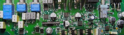
I tried to attach a picture of the inside of the amp, but I guess it is to big of a file, I tried resizing it, but I still could not get it right, but I do have pictures of the inside of the amp, fairly high quality images, I could probably email them if needed. Oh well, I tried!
Here is what the amp does / what I checked: It powers on but produces no sound. The power supply is operating fine as it is generating about +/- 59 Volts on the rails. I checked the output transistors (in circuit) & they seem to be fine, though I should probably remove them for proper checking, but again, I think there ok. I tested the voltage on the op-amps and it is about +/- 17 - 18 volts, one thing I thought was strange, though may not be a problem, is the Positive voltage on the op-amps is about +18 volts & the negative voltage on the op-amps is -16.97 to -17 volts, seems like it should be the same voltage for the +/-, but that may be normal and not far enough off to be an issue. I used the ground terminal on the amp for my reference. Maybe I should be using something else as my ground reference?
There are a couple large surface mount resistors that get hot after the unit is on for about 1 minute, there are also some large surface mount transistors that get hot after about 1 minute, that may be normal, but they get hot enough I can not touch them for very long. The power supply & output transistors stay cool to the touch. I did all the checks with current limiting resistors to help prevent damage while testing. I also did some probing on some large surface mount transistors on the op-amp side of the filter caps & some of the voltages seemed a little high on 2 compared to another one next to them, though when it comes to correct voltages on transistor in those areas I am not exactly sure what I am looking for, so that bit of info may be useless.
At this point I am not really sure what to check, I am still learning, and the surface mount parts are a little different than the through hole components I am use to. I am thinking maybe some transistors in the driver stage are bad, & possibly the protection circuitry is active? There is no DC on the speaker terminals, but if there is DC protection that would be why. Again, I am not really sure what to check or what I am looking for from here, maybe someone can point me in the right direction as I would like to repair this amp, & this amp will be perfect for learning on.
Since at this point I am not sure what to check, what exactly should I be looking for in here, how do I know if the protection circuit is on? If the protection circuit is on, if I new how to disable it, it may be easier to trouble shoot with it temporarily disabled, as that is what I did to a Coustic 600SE to find a bad driver transistor that was causing DC on that channel, it was much easier finding the problem after the protection circuit was disabled, though that amp was a little easier to work on as it uses mostly through hole components. So how do I locate the protection circuit?
MTX told me they will not release schematics, so thats out.
Ok, I thank everyone who took the time to read all of this & anyone who replies back with some info! I hope I covered everything. I look forward to getting some help!
Kyle
I tried to attach a picture of the inside of the amp, but I guess it is to big of a file, I tried resizing it, but I still could not get it right, but I do have pictures of the inside of the amp, fairly high quality images, I could probably email them if needed. Oh well, I tried!
Very nice powerful amp, I hope you get it figured out. I had one I had to send to mtx because it was too difficult for me to figure out. Mine had bad ouputs and some preamp problems. Yours sounds like its just in the preamp section. That amp most likely puts out around 750 watts rms. All of the ones we sold put out WAY more than they were rated. Nowadays they barely put out more than the rated power.
Do you have audio on pin 1 of the op-amp near the 4 conductor connector on the corner of the board?
Are any of the op-amps getting too hot to touch?
The NE5532s run warm but should not be too hot to touch.
Also, may sure that ALL of the op-amps have plus/minus supply voltage. There are resistors that open and break the connection to the op-amps.
The difference in the regulated voltage isn't a big concern.
ppia600: Thank You for the reply! I have not had the opportunity to hear a 6500D yet, though they look like nice amps, & the guy I bought it from told me they were way under rated and do put out a lot of power. I bought this amp and a few others from a guy locally for parts or repair, I repaired the legacy LA1880 (I think that was the model) fine a while back & the old Pyramid seemed fine other than was missing some screws, but the MTX 6500D amp I have not been able to fix yet, it has just been laying around here getting moved around & I figure it is about time I fix it. To bad you had to send one of yours to MTX to fix, I hope I will be able to fix this one as I need the learning experience from this type of amplifier, if I can't fix it I will probably keep it for parts or sell it to someone who can, though I want to try my best at fixing it before I give it up that easy, so I hope for the best! It does seem amps nowadays barely put out more than there rated power, like Rockford Fosgate amps I have seen the birth sheet on, I have seen some of the newer 800 watt 2 channel amps barely put out much more than 800 watts, I have a brand new in the box Rockford 800a2 and it's birth sheet is like 1028 watts or something (it has been a while since I looked at the sheet on mine new one, but it is over 1000), quite a bit different than there newer ratings, my other 800a2 I repaired has do 900+, though I do not have the birth sheet for it. I sure do love repairing and testing amplifiers!
Perry Babin: Thank You for the reply! I think I checked the correct op-amp you are referring to. I will try to attach a picture again, though the quality is not as good since I cropped & resized it and changed the color quality. If I attach the picture ok, the op-amp I believe you are referring to is the farthest one to the right in the picture; I get virtually NO audio output on pin-1, I can see the very slightest bit of audio on my scope, I almost did not notice there was an audio signal there, but nothing like the op-amp by the RCA connectors that I also checked for audio output on.
Most of the op-amps seem to get pretty warm, though the one just to the left of the one I tested for audio on gets pretty darn hot, I can hold my finger on it most of the time, but it is pretty hot, I would say pretty much to hot to touch, I also checked that one for audio with my oscilloscope on the outputs and it has (-) 15.5 vDC on the outputs pin-1 & pin-7, as I then checked it with my DC Volt meter to see why it was not an audio reading on my scope. So maybe that op-amp is faulty or something before it in the path? Are there other op-amps I should check for audio input / output on?
All of the NE5532's have Plus / Minus Supply Voltage on there V+ & V- inputs.
Thanks again ppia600 & Perry Babin for the replies, I am learning more!
Attachments
If the op-amp is too hot to hold your hand on and is significantly hotter than the others, it's either defective or being loaded heavily. If you have a replacement and can remove it without damaging the board, replace it. I've seen a lot of them fail in this way and although using the temperature to find the defective one isn't 100% foolproof, it works most of the time.
Thanks for the fast reply Perry Babin! I do not have any NE5532's on hand, so I will have to order some. By any chance do you know a supplier that carries them that does not require really large quantity orders? I checked digikey & mouser, they seem to carry them, are there any others?
I am not sure when I will be able to order any parts so it may be a while, though when I order them for this amp, I will buy parts for one of my personal amps that need new output transistors.
Are there other things I should check on the 6500D that could also be bad that I may need to order as well, or should I wiat until I order the NE5532's to see if that is the only problem?
I think I will be able to remove and replace the NE5532 ok, though it is very small. I did some work on a keyless entry remote for a car, and had to remove the surface mount I.C to repair some traces after the battery jammed into the I.C and partially ripped it off the board, The remote worked for a while after the repair, but the traces were damaged badly, and I guess my repair was not the greatest, I repaired it twice and did not attempt it again after it went out, though I could probably get it working again if I had to. If the traces were not so badly damaged, I think it would of went smoothly just replacing the I.C.
Thanks Again for the reply / info!
Check the solder connections on all of the large surface mount transistors.
The VCA (Voltage Controlled Amplifier) sometimes fails and produces a DC offset but I think this amp may have a DC blocking capacitor in series with the VCA's output. This was a revision they made to some of their other amplifiers. If there is no capacitor in series with it, it could cause DC offset (if it's defective).
Mouser has the NE5532D for $0.80each. Mouser and Digi-Key are your best choices (in my opinion) unless you want to buy large quantities.
If you're not sure you can replace the IC without damaging the board, buy the smallest quantity of ChipQuik available (or order a sample from the company if you can wait a week or so). It's a low temp alloy that will allow you to remove the chip with less heat. You solder the IC back in with normal solder.
Perry Babin,
I made a mistake when I checked for audio on pin-1 of the op-amp by the 4 conductor connector you asked me about. The reason I was not getting any or very little audio on pin-1 was because I had the amplifiers gain potentiometer all the way down from the last time I did tests on the amp! I feel like an idiot! As soon as I turned up the gain, the I.C was putting out audio. So the op-amp you asked me about does put out audio on pin-1.
The other op-amp to the left of that one is of course still getting hot, but it looks as if its inputs are connected to one of the large surface mount transistors by it, maybe thats why it puts ( - ) 15.5 VDC on its outputs? Possibly suppose to do this? Looks like it feeds some very small transistors at its outputs.
I checked the solder connections on the large surface mount transistors and they all look good so far.
I beleive the VCA (Voltage Controlled Amplifier) you are refering to is the THAT 2155 I.C? I viewed the datasheet for it, but how should I check it to see if it is not operating properly, should I look for DC on the input / output pins?
Ok, just wanted to give an update to my previous error! with the amps gain control.
Also, I looked at the ChipQuik you mentioned. I read about it and it looks like some nice stuff, I might have to get some when I need it, as it seems it may make removing the surface mount I.C's really easy and clean. Thanks for the tip on that stuff!
If I'm not mistaken, when the amp is muted, the audio on pin 1 (maybe pin 7) of that op-amp has rail-rail clipped audio and as the muting is released, the signal no longer is driven to clipping. Does the signal change on yours a few seconds after you apply remote (after the mute delay)? Check both pin 1 and pin 7.
If you're getting audio to the op-amp mentioned above, the VCA is OK (or, at least working well enough to pass audio).
Is there any oscillation on the output FETs?
The op-amp that's overheating could be the output buffer for the preamp output jacks just to the left of the IC. The outputs are connected to diodes (circuit board designation D80 and D81 -- the D tells you it's a diode).
Perry Babin:
Yes, I do have an oscilloscope. I was just wondering where exactly to connect it to the output fets. As I stated before, I am still learning, so I just want to make sure I am doing proper tests how it is suppose to be done and connecting my equipment to the propper test locations. I have probed the output fets with my scope when I was doing checks last time, if I had the scope connected properly, I did not see any oscillation when I had the scope on the output fets. I beleive I probed the center pin on the output Fets. I will check again later today or tomarrow when I get a chance, again I just want to make sure I am doing this correctly. Thanks again for your help!
Yes, I do have an oscilloscope. I was just wondering where exactly to connect it to the output fets. As I stated before, I am still learning, so I just want to make sure I am doing proper tests how it is suppose to be done and connecting my equipment to the propper test locations. I have probed the output fets with my scope when I was doing checks last time, if I had the scope connected properly, I did not see any oscillation when I had the scope on the output fets. I beleive I probed the center pin on the output Fets. I will check again later today or tomarrow when I get a chance, again I just want to make sure I am doing this correctly. Thanks again for your help!
There are two pairs of FETs. One pair will have it's middle leg connected to the other pair's third leg. Those are connected to the input of the filter inductor. All of these should have rail to rail oscillation.
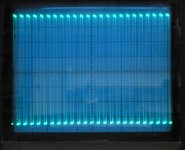
The following was taken from a similar amp (MTX 250D). This is the type of oscillation you should see. The timebase is set to 10us. The Vertical amp is set to 10v/div. You may have to go a bit higher (20v/div) for the 6500D.
The following was taken from a similar amp (MTX 250D). This is the type of oscillation you should see. The timebase is set to 10us. The Vertical amp is set to 10v/div. You may have to go a bit higher (20v/div) for the 6500D.
Attachments
Ok, I finally got a chance to do the checks on the amp.
Here is what I checked: I checked the audio on pin-1 of the op-amp to see if it changed after remote was applied, it appeared to be heavily clipping and did not change at all as I monitored it. I checked pin-7 and the waveform looked clean but also did not change any after the remote was applied.
I checked the output transistors for oscillation as you asked and it is not oscillating, I probed around the area to see if I could find anything that was oscillating that is connected to the output transistors & nothing else seemed to oscillate either. As I probed around the outputs again it looked like there was some oscillation starting so I checked the outputs again and they were oscillating for a moment, but then stopped and I have not seen oscillation since, not sure what that means.
When you mentioned the MTX 250D I remembered I also have an MTX RT251D, which is probably similar to the 250D. I repaired the RT251D a while ago and that amp only had 1 bad output FET, which of course was an easy repair replacing both FETS after I found the problem. That little amp worked fantastic in my sister’s car for months when she used it, and it still works great! Though it has been sitting in a box for a while.
Anyway, I opened the RT251D up so I could see the oscillations on the output FETS that you showed me in the attachment. The amp oscillates just like the one in the picture. I am glad I got to see the oscillation first hand on the RT251D, as it makes it easier knowing what I am looking for. The RT251D is very similar inside compared to the 6500D, though much, much smaller.
But again, the 6500D did not oscillate on the outputs. Maybe the amp is muted as it has continuous clipped audio on pin-1 of the op-amp.
Perry Babin: Thank You for all of your help!!! It is Greatly appreciated!
This is a self-oscillating class D amp so it won't have any oscillation unless there is oscillation on the outputs.
Push the output transistors to the side (gently) to see if any of the legs on them are broken. They sometimes break where the leg enters the body of the transistor.
While the amp is on, move/twist the inductor near the outputs. If it's shorted, it could cause the amp to go into protection. I don't know if the overcurrent protection is latching so you should try disconnecting and reconnecting the remote input to see if it begins to oscillate after moving the inductor.
There are two 475 ohm resistors (R140/R142 -- marked 4750) near the large surface mount resistors. What is the DC voltage across each one? Check it with and without signal.
I checked the legs on all of the output transistors and none of the legs appeared to be loose where they go into the body as I gently moved them.
I tried to move/twist the inductor by the output transistors, though it did not really move as it looks to have light coating of glue on it. I disconnected and reconnected the remote to see if it made any difference but it did not start oscillating. One thing I noticed is when I first apply remote to the amp I see what looks like light oscillations starting, but fades back out a little over 1 second later, it does this every time I connect the remote lead.
I checked the DC Voltage on R140/R142, if I did it right. I connected my volt meter probes on each side of the resistor under test, so basically I had the probes across the resistor. Maybe I checked them wrong. (NOTE: the large surface mount resistors by R140/R142 get extremely hot, may be normal for them, but it seems a little to hot for there size)
Here is what I got:
R140) – 0.00 VDC with & without signal)
R142) – 0.00 VDC with & without signal)
Check the following components with the amp off then measure the DC voltage across them with the amp on (no signal). For the transistor, measure the voltage from base to emitter and from collector to emitter.
D106
R133
Q110
R112
These are part of a constant current source. If there is no voltage across those resistors, the CCS probably isn't doing its job.
D106
R133
Q110
R112
These are part of a constant current source. If there is no voltage across those resistors, the CCS probably isn't doing its job.
Hi all
I have the same amp in my pickup, and some times is muted, no have audio but the amp still on after it silent completely,
but I corrected the problem when solder the "bad joints" pads of the sot-223 A56 A06 and sot-23 2G 1G transistors
sot-223 trans produce to much heat, and transfer it trough pcb and some opamps, making hard to troubleshoot.
Hello everybody! Just want to note: I have been very busy working and have not had time to post new info on the 6500D, have not really had time to work on it. I am hoping within the next few days or within a week I will have some time, but for now it will have to wait. I have not given up on the amp, & I will post back all of the new info on it when I get the chance. Thanks again for everyone’s input & help, it is greatly appreciated!
Hi everyone!
Just kicking a dead horse here as I have one now that does the SAME thing (no output) Did the original poster get anywhere with his?
Following along this post I confirmed and did the following:
1) PS good and all rail voltages present at outputs.
2) All voltages present at *every* op-amp +/-17 volts.
3) Reflowed solder on large SOT parts
4) Checked for self-oscillation via perrys diagram - Nothing!
5) Checked for clipped audio @ pin 1 of op amp near high level input - Yes!
6) Measured *across* R140 & R142 and the potential was .07 volts
7) Measured each end of R140 & R142 with PS ground as reference and got over 80 volts on all ends. I assume this is what Perry meant by 'across' actually.
I inspected for physical damage to the output filter and found nothing remarkable. Also found no physical damage anywhere else. I pulled and tested the outputs and they are fine. If I put a scope on the output and run signal through it a modulated version shows up at the output that varies in intensity with the gain. Trouble is you need a pair of headphones just to hear it! The clipped audio @ pin 1 of the mentioned op-amp will also vary it's width with gain adjustment. From what I am reading this means the amplifier is being muted for some reason. Where do I go from here? Thanks!
- Matt
- Status
- This old topic is closed. If you want to reopen this topic, contact a moderator using the "Report Post" button.
- Home
- General Interest
- Car Audio
- MTX 6500D - No Output