How much interest is there in power supplies for DIY car audio amplifiers?
This was mentioned before. How many of you would be 'really' interested in a supply that could support an amplifier of ~400-500 watts?
If there is enough interest, I may be willing to build them or to provide the main components (sink, board, transformer), with detailed assembly instructions. The prices would be ~$110 for the main components and ~$160 assembled.
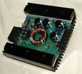
This is the prototype. I ran an amplifier on it and it produced ~$500 watts into a 4 ohm mono bridged load.
This was mentioned before. How many of you would be 'really' interested in a supply that could support an amplifier of ~400-500 watts?
If there is enough interest, I may be willing to build them or to provide the main components (sink, board, transformer), with detailed assembly instructions. The prices would be ~$110 for the main components and ~$160 assembled.
This is the prototype. I ran an amplifier on it and it produced ~$500 watts into a 4 ohm mono bridged load.
Attachments


I don't know anything about the one you posted.
The output voltage on the one I posted could be virtually anything you need. The transformer in it is wound 3:1. It's a good general purpose ratio. With this transformer at 13.5v DC in, the output is ~±40v (unregulated). There is regulation for the rail voltage but I'll modify it a bit in the next run. This one only monitors one rail. I generally monitor both rails and should have here.
There are pre-regulators so you don't have to worry about going too high for the linear voltage regulators in it (7815/7915 IC regs).
The current would vary with the ratio of the transformer. The total power output could be set conservatively at 400 watts RMS.
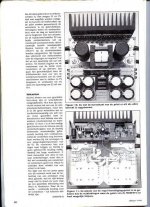
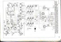
The elektor supply is more sophisticated. It would be difficult to build unless they supplied the transformer. If you can buy the transformer, it looks like a nice supply. From what I could tell, it has higher-than-rail supplies for the drive section of the audio amplifier. It also uses opto-couplers for regulation.
Perry Babin said:The elektor supply is more sophisticated. It would be difficult to build unless they supplied the transformer. If you can buy the transformer, it looks like a nice supply. From what I could tell, it has higher-than-rail supplies for the drive section of the audio amplifier. It also uses opto-couplers for regulation.
I've the full manual to build it +PCB layout and how to build the transformer and step-down transformer.It's from the year 1994 and at that time I did want to buy it but I didn't
 Its a regulated supply with 43Volts/DC output and 50A current
The current draw depends on the power drawn from the secondary. At idle with no load, it draws ~1 amp. The current draw at higher power will vary.
If the elektor states that it draws 50 amps, it should state the output current.
I haven't shipped any as of yet. I had 5 boards printed so I could test it. If I'd ship it to Europe, I'd have to ship it via a trackable shipper (FedEx, UPS...).
This supply doesn't have an isolated secondary. The elektor does. I'll likely have an option for an isolated secondary on the next set of boards.
If your amp design doesn't have noise cancelling inputs, you could have noise problems using this supply (due to ground loops). You could break the loop of you use a ground loop isolator (transformer) in the signal line. If you didn't need regulation, this secondary could be cut free from the main ground.
If you're interested, these are some of the features:
*Size ~6"x7"x2.75" (1" longer with the bottom cover -- which includes mounting brackets)
*Double-sided FR4 fiberglass circuit boards
*High quality snap-mount caps for the main rails
*Low ESR caps across the B+ supply
*8 FETs in the supply (IRFZ44s are in the prototype)
*Pre-regulators to allow the use of IC regulators (which have limited input voltage -- generally 35v) when the supply is used for high rail voltage
*±15v regulation to power the preamp section of an amplifier
*Terminal blocks for input and output
*Regulation for the main supply (of limited use at this time)
*Thermal protection
*Overcurrent protection in the form of fuses for the rails (linear regs have their own protection)
*A thermally controlled fan output
*Film bypass capacitors on nearly all electrolytics
*RC snubbers on the power supply primary
*High speed, heatsink mounted rectifiers
DIY bonus features:
*LED indicators to let you know the drive circuit is oscillating without a scope
*LED indicators for each output
*The pre-regulators can feed gainclone modules while the main rails power a subwoofer amp
*Generous pads and vias to help prevent board damage (for those who like to experiment with different values of components)
*The traces on the rails are designed to be cut to allow you to insert an inductor or resistor for those who want CRC or CLC supplies
I'd just like to say -
Perry, that is one neat construction.
Very impressive.
Looks better than any commercial amp/supply I have seen - And I've seen a few.
Wish I had the money.
I've an idea for a really nice amp that would be configurable from 1 channel to whatever is needed, each channel is ~75wrms.
Your supply would be perfect.
Best of luck with it...
I thought about building everyting for an amplifier except the audio driver section (which would be built by the DIYer on a vertical daughterboard). This would include the output transistors, emitter resistors, protection circuits, power supply and anything else that would be needed to build a nice amp. The problem, as always, is cost.
One of the amps I use is a common emitter and it uses an op-amp in the feedback loop. It's generally used as a 750-800 watt amp (~400 watts/channel into 1 ohm). The other is a common collector. It's all discrete. It's been set up as a 350 watt amp (175/channel into 2 ohms). The output of either can be scaled by changing the rail voltage.
The supply has regulation and works perfectly when current is drawn from both rails (as when driving a bridged amplifier). If the regulation is cut back too far and is driving a tough, unbalanced load, the regulation isn't stable. It could likely be improved but I'm not concerned about it. It works perfectly unregulated. I'll change the regulator for the next set of boards.
What voltage do you need for your amp?
The boards cost me ~$25 each (prototype quantities are expensive). The transformer would be another $10. I wouldn't sell it without the transformer because that's the one thing that is most problematic in a supply. If you wanted one of these, I'd sell it (bare board with transformer installed and tested) to you for $35 plus shipping (likely to be expensive via FedEx or UPS).
I'm waiting on cores as of now. I'm hoping to get them by early next week.
I have two amplifiers,they are working with a sym. voltage of 35Volts.Does your supply has sym.output-voltage?
Do you have pictures or schematics of your amps?
About the parts of the supply are you using commen parts?
The $35 is that for the PCB and transformer without the components.I send you an Email if I want to order and let you know what parts I want,if that's OK by you?
Do you have pictures or schematics of your amps?
About the parts of the supply are you using commen parts?
The $35 is that for the PCB and transformer without the components.I send you an Email if I want to order and let you know what parts I want,if that's OK by you?
Sym = Symmetrical? The supply produces plus/minus 40v (unregulated, 13.5v input). It also produces plus/minus 15v.
I don't have schematics for the op-amp based amp. I'm not willing to post the schematic for the other amp.
The parts in the supply are common here, you'd likely be able to get them there also.
$35 for only the board and the transformer, no other electrical components. I'd include the terminal blocks also.
Before you decide if you want it, go to the FedEx or UPS sites and get a price from here (zip code 70737) to your address. The shipping service must require an adult signature for delivery.
- Status
- This old topic is closed. If you want to reopen this topic, contact a moderator using the "Report Post" button.
- Home
- General Interest
- Car Audio
- Car Amplifier Power Supply