I just finished recapping my second am radio. After the first recap was a success I was thinking no problem now. HA!
Guess again...I had no problems replacing the caps in the second radio except when I put everything back together again and went to bench test it.............nothing. I checked all of the wiring and all of the solder joints look fine. All values are in line with the originals too. The only thing I can think of was that when I replaced the 3 caps that were in a can originally Sam's called for 2 caps=400uf/16v and 1 cap 100uf/16v. I replaced them with 2 caps=500uf/50v and 1 cap 100uf/50v. Are the two larger caps too high in uf and would this cause the radio to not function at all?
As always thanks for your help guys !
No, the radio should function just fine with the caps you put in. You likely have a problem somewhere else. Based on 2 @ 400uF, 16V, it sounds like those are +/- rails for a bipolar power supply. Verify, it it is a switching power supply, that you are getting AC through the transformer.
Also check for blown fuses, rectifiers, etc.
Also check for blown fuses, rectifiers, etc.
zigzagflux said:No, the radio should function just fine with the caps you put in. You likely have a problem somewhere else. Based on 2 @ 400uF, 16V, it sounds like those are +/- rails for a bipolar power supply. Verify, it it is a switching power supply, that you are getting AC through the transformer.
Also check for blown fuses, rectifiers, etc.
Thanks for your reply ZZ. You see, that's just the thing. I'm so new at this that I don't know what to look for when you say rectifier, fuse or switching power supply. I'm really new at this so I'm learning as I go. I guess this qualifies for "something new". Any tips or suggestions? Thanks
65blkbkgt said:I don't know what to look for when you say rectifier, fuse or switching power supply.
That will certainly make things difficult. Any way you can take a picture of the guts? I could probably try and identify some critical parts.
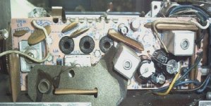
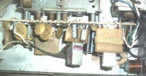
I took the radio apart again on Thursday and checked for loose connections etc. and still nothing. Before I put it back together again I still had it hooked up and touched the output transistor to the radio case and got some static? Anyway I changed the output transistor, put the radio back together and again.....nothing.  I need help...please....anyone?
I need help...please....anyone?At this point I would say you got one shot at this working, and that is to get the power supplie(s) working. Anything beyond this is probably a little too complex for the beginning techie, and will most certainly be impossible for anyone to help out without a schematic.
You are looking for DC supplies, maybe just 15V, maybe bipolar supplies (plus and minus 12V). Measure across the two leads of the larger uF capacitors, and see what you get. Your caps will be labeled with negative terminals. Connect your black lead of the multimeter to the negative terminal on each cap.
Report back.
zigzagflux said:At this point I would say you got one shot at this working, and that is to get the power supplie(s) working. Anything beyond this is probably a little too complex for the beginning techie, and will most certainly be impossible for anyone to help out without a schematic.
You are looking for DC supplies, maybe just 15V, maybe bipolar supplies (plus and minus 12V). Measure across the two leads of the larger uF capacitors, and see what you get. Your caps will be labeled with negative terminals. Connect your black lead of the multimeter to the negative terminal on each cap.
Report back.
I took the multimeter and got ready to try what you instructed. What I found as I was checking the large caps is that one of the solder joints on one of the caps pulled loose from the board.
Okay I'm going to describe this in laymans terms so bear with me here.......
On the back of the board (where the solder joints are) the positive goes through the board and is soldered but there is a metal piece originally attached to the board which came loose. Is there any way of attaching that back to the board? I think this may be my problem?
Btw......I do have the schematic for this radio.
65blkbkgt said:Btw......I do have the schematic for this radio.
Gadzooks, by all means, scan and post it !!
The metal piece you are referring to is called a circuit board trace. It is the "wire" of the circuit board. You absolutely need to ensure it is connected.
The problem you describe is not uncommon when unsoldering components. Get the trace a little too hard, or pull hard enough, and it de-laminates from the fiberglass board. I suggest placing it back where it belongs, and running the capacitor lead through the hole that should exist on the end of the trace. Once everything is soldered, you have an electrical connection, and you'll be fine.
If the trace breaks, you'll have to use some thin wire (24 to 30 gauge) to replace the trace where it was broken. Again, pictures help if you need more instruction.
Good luck
zigzagflux said:
Gadzooks, by all means, scan and post it !!
The metal piece you are referring to is called a circuit board trace. It is the "wire" of the circuit board. You absolutely need to ensure it is connected.
The problem you describe is not uncommon when unsoldering components. Get the trace a little too hard, or pull hard enough, and it de-laminates from the fiberglass board. I suggest placing it back where it belongs, and running the capacitor lead through the hole that should exist on the end of the trace. Once everything is soldered, you have an electrical connection, and you'll be fine.
If the trace breaks, you'll have to use some thin wire (24 to 30 gauge) to replace the trace where it was broken. Again, pictures help if you need more instruction.
Good luck
Hmmmmmmm........I checked the connection again and the cap is soldered to the trace but the trace is just pulled away from the board. Shouldn't it still work?
- Status
- This old topic is closed. If you want to reopen this topic, contact a moderator using the "Report Post" button.
- Home
- General Interest
- Car Audio
- Stumped on 2nd Re-Cap and need help