I received a boss ava-650 from a coworker for $10. One channel was bad, opened it up and one power supply had cooked! Aside from that, on the same channel, the output terminals were melted. Someone had messed it up good.
Rather than trying to fix the dirty beat up amp ( way too much wattage for me anyway), I parted it out. I got a KIA494 from it ( TL494). I also got four ultrafast diode pairs, two 1 inch torioids, and 4 good IRFz24's. While the z24's aren't exactly what I would use for this use due to low current rating and high z_on, I can use them for prototyping. I have two stp55n06's that I can use in a more serious amp.
I am really only needing 60 watts or so.
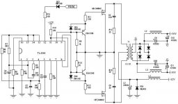
I have some schematics for some amps with the TL494 in it. It does not seem too complex, but the lack of ability to direct drive the mosfets means adding two small transistors.
For prototyping purposes and getting my first smps up and running, should I use the 494 or should I just order a 3525?
TSD88~
Rather than trying to fix the dirty beat up amp ( way too much wattage for me anyway), I parted it out. I got a KIA494 from it ( TL494). I also got four ultrafast diode pairs, two 1 inch torioids, and 4 good IRFz24's. While the z24's aren't exactly what I would use for this use due to low current rating and high z_on, I can use them for prototyping. I have two stp55n06's that I can use in a more serious amp.
I am really only needing 60 watts or so.
I have some schematics for some amps with the TL494 in it. It does not seem too complex, but the lack of ability to direct drive the mosfets means adding two small transistors.
For prototyping purposes and getting my first smps up and running, should I use the 494 or should I just order a 3525?
TSD88~
Either will work well but here are some things you should consider.
If the supply will be really simple (no regulation, no thermal protection, no more than a total of 4 FETs...), the 3525 will make the layout and construction a bit easier. Since there will be no buffer for the 3525, it may be damaged if the FETs fail. Mount it in a socket. It will be easier to replace.
The 494 has 2 error amps. If you 're going to use regulation AND thermal protection (using a thermistor), the 494 will be better. One error amp can be used for each function.
The 3525 has a soft start function. For small supplies, it's not really needed but it's easy to use if you want soft start. It can be done with the 494 but not as easily.
When you're building your first supply, you should use new FETs. If the FETs are not 100% OK, it could cause you to spend a lot of time troubleshooting the circuit.
I am not going to need any regulation as I don't see the need for it with a small amp like will be connected. Thermal protection might be something I would consider, but again I design my amps with enough heatsink. The STP55ne06 FETs should'nt but merly get warm to the touch with a supply this small. I know that the 3525 will definatly make the layout simpler, and I am going to order a few regardless sometime. Its just that I have the 494 to experiment with right now. Also, the STP55ne06 came from a working UPS backup unit. I figure if I fry something with my bench supply oh well, I'll buy new parts for the 'real' project. Better to fry freebies than ones you paid for!")
About the transformer: How do I know what frequency to operate it? Should I just shoot for between 50 and 100khz or does it really matter? The transformer used 22 AWG magnet wire for both the primary and secondaries.
About the transformer: How do I know what frequency to operate it? Should I just shoot for between 50 and 100khz or does it really matter? The transformer used 22 AWG magnet wire for both the primary and secondaries.
I'd suggest running it at ~30kHz. For the TL494, a 1000pf cap and a 20k ohm resistor will give you approximately 30kHz.
For testing, connect pins 1 and 16 to ground.
Connect pins 2 and 15 to pin 14 (5v).
Connect pin 13 to pin 14.
Connect pin 4 to ground.
Pin 7 is ground.
Connect pins 8 and 11 to B+ (through a 1 ohm resistor for protection of the IC).
Pin 12 can be connected to B+ for testing. It would need to be connected to a switched source later.
Pins 9 and 10 will drive the FETs or driver transistors. If you want to use the IC without driver transistors, you can use a 2 watt resistor between 51 and 68 ohms as a pulldown resistor on the outputs of the IC. The resistors will run a bit warm. This will be OK to drive only 2 FETs (one per output). If you use more FETs, you'd need to use driver transistors.
You should use 3-4 strands of 22g in parallel for the primary windings. I don't know what core you have but 4+4 on the primary would be a good starting point.
The 1" toroids were likely filters and won't work well for a transformer core.
no, they were the transformers. They were the only transformers on the board, and the primaries went to the fets and the secondaries went to the UF diodes. The actual size is 1 1/4 inch OD, 3/4" window, and 5/8" heighth. I know they are small, but they should be good for about 100 watts each and will work for testing purposes.
For wire, all I have is 22agw magnetic wire from the shack, so I am going to strand it ( 2 or 3 strands) and then wind it.
Should I interwind the primary and secondary or do I not have to? It seems that on Rod's site , in the picture he has he just had the primary and secondary on seperate sides.
For wire, all I have is 22agw magnetic wire from the shack, so I am going to strand it ( 2 or 3 strands) and then wind it.
Should I interwind the primary and secondary or do I not have to? It seems that on Rod's site , in the picture he has he just had the primary and secondary on seperate sides.
I wound 4-0-4 turns on the primary of dual stranded 22awg. When I power up , I can't even keep the B+ line connected to the bench supply without it melting and a FET burning. while underpowered, The fets I was using were good ( IRFz24n). I did not have a load on the supply so the FETs should not have burned...
By the way I am using KTA1023 transistors as fet drivers.
By the way I am using KTA1023 transistors as fet drivers.
That circuit looks OK.
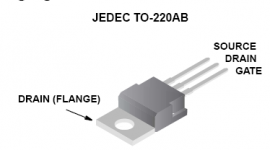
Remove the transformer and connect a 1k ohm resistor between B+ and the center leg of each FET. With the power supply powered up, measure the DC voltage on the gates and the drains (the center legs). They should all read ~1/2 B+. The black meter lead should be connected to ground for these measurements.
Remove the transformer and connect a 1k ohm resistor between B+ and the center leg of each FET. With the power supply powered up, measure the DC voltage on the gates and the drains (the center legs). They should all read ~1/2 B+. The black meter lead should be connected to ground for these measurements.
If you connected the drain directly to the B+ line, you should have blown the fuse. When the FET switched on, the B+ would have been shorted to ground.
Disconnect everything from the outputs of the IC except the 1k pulldown resistors. If you measure the DC voltage on pins 9 and 10, what do you get?
Check the FETs. There should be absolutely no continuity from the first leg to either of the other legs.
Disconnect everything from the outputs of the IC except the 1k pulldown resistors. If you measure the DC voltage on pins 9 and 10, what do you get?
Check the FETs. There should be absolutely no continuity from the first leg to either of the other legs.
If I remember my voltages from earlier correctly, on the order of ~4.5vdc on each pin. No continuity on the fets... My DMM measures anything below 100 ohms as a short. And no I did not connect the drains to the B+, I connected them to ground. My primary center tap went to the B+ and the two other leads to each FET.
To find the problem, you need to take it step by step.
You need to recheck the output voltage on pins 9 and 10 again. Remove all external circuitry from those pins except the pull down resistors. Confirm that the voltage was indeed ~1/2 B+. Take nothing for granted.
Next add the driver transistors and diodes. Recheck the voltage on pins 9 and 10. Also check the voltage on the emitter of the driver transistors. It should also be ~1/2 B+. Confirm that it's the same on both drivers.
Next connect the FETs to the drivers. Connect the source of the FETs to ground (as usual). Connect the drain to one end of a 1k ohm resistor. Connect the other end of that resistor to B+. Recheck the voltage at the driver/gate connection. It should still be ~1/2 B+. If that's OK, check the voltage on the drain of the FETs. They should also be at ~1/2 B+. The voltage across the two drains should be ~0v DC when the power supply is in operation.
Switch your meter to AC volts and measure the voltage from ground to the drain of the FET. Now measure the AC voltage between the drains of the FETs. The voltage between the drains should be ~2x the voltage from ground to either drain.
If all is precisely as it should be, then you know that the problem is almost certainly in the transformer.
When checking for continuity between the gate and the other legs of the FETs, you should set your meter to ohms. If there is anything other than infinity ohms (OL on most meters), the FET is defective.
ThSpeakerDude88 said:No I did not connect the drains to the B+, I connected them to ground.
There's your problem, your suposed to connect the source to ground and the drains to the transformers primary. The way you have it puts them backwards and the reverse diode in the fet is forward biased, so that diode take all the power from your bench supply and goes poof.
Attachments
Originally posted by ThSpeakerDude88
I also got four ultrafast diode pairs, two 1 inch torioids, and 4 good IRFz24's. While the z24's aren't exactly what I would use for this use due to low current rating and high z_on
I've never understood why so 'little' or weak switching devices are used in some common (can i say high power?) amps like in here...
Rdson is a bit high i think, even if you pair a couple of it... Ok you have to build it as cheap as possible if you plan to sell it in big amounts.
My car amp design which will be tested soon as i have some extra free minutes will use 2-2 (or 3-3
 ) buk755r2's to drive the primaries, although it's design power is somewhere between 3-350W in best case 400W continuous...
with nothing connected to pins 9-10, I get 4.5 and 4.34v respectivly. With the Driver transistors and diodes I still get about 4.3v. However, the weird part occurs when I connect the fets through a 100 ohm resistor. When I measure the voltage at pin 10, i get 1.3vdc. When I measure the voltage at pin 9, I get 3.97vdc.
Edit: I forgot to put in the pulldown resistors for this test. The bottom one reads the same ( pin 9) but pin 10 reads only 200mv or so with the pulldown resistor. Is the chip bad?
Edit: I forgot to put in the pulldown resistors for this test. The bottom one reads the same ( pin 9) but pin 10 reads only 200mv or so with the pulldown resistor. Is the chip bad?
ok well I connected it like you said to before with the 1k resistor between b+ and the drains ( FETs in correctly this time.) on the FET that is being driven by pin 9 , When i measure the voltage @ the drain I get 5.69vdc ( half of B+ like you said I should read.) However, when a load is placed on the other FET ( driven by pin 10) its driving voltage at the 494 drops to half a volt, and my drain voltage is 12.4v.
These measurements were taken with the STPNE06 fets.
With the irfz24's , the one that is working correctly measures 6.04v at the drain which is exactly what it should be measuring. The upper one will however merasure around 9.8v.
These measurements were taken with the STPNE06 fets.
With the irfz24's , the one that is working correctly measures 6.04v at the drain which is exactly what it should be measuring. The upper one will however merasure around 9.8v.
- Status
- This old topic is closed. If you want to reopen this topic, contact a moderator using the "Report Post" button.
- Home
- General Interest
- Car Audio
- Low Power: TL494 or SG3525?