

This is just an area I can blab on about stuff without it using up bandwidth in the threads  Hopefully someone will find it interesting or useful.
Tony.
Hopefully someone will find it interesting or useful. Tony.

Synergy "Active" Crossover
Posted 6th April 2010 at 12:38 PM by wintermute
Updated 5th January 2011 at 03:18 AM by wintermute (fixed a couple of typos, and added a small amount of clarification.)
Updated 5th January 2011 at 03:18 AM by wintermute (fixed a couple of typos, and added a small amount of clarification.)
Following on from YARPS I thought I would post the design I have been working on for my active crossover (which is in fact is what the YARPS power supply was designed to drive).
So here I present the Synergy "Active" Crossover. Please note I have only simmed it at this stage (and when I started I knew nothing about active filter design) so there is no guarantee it will work.
Why have I put "Active" in quotes? Because whilst this filter uses active components, for all intents and purposes it behaves like a passive filter. It basically emulates either an LC or a CL passive 2nd order filter.
Why the name Synergy? Well I though it was the best word to describe the differing technologies working together to give the end result
The design goal is to have an active crossover that for all intents and purposes is transparent. That is it does nothing other than split the frequencies at the desired crossover point.
For simplicities sake I went with second order and I decided on a Linkwitz Riley alignment. I had toyed with the idea of doing a Bessel alignment (due to the benefits it provides in transient response) but in the end decided that the LR was a good compromise between transient response and pass-band flatness (probably the conclusion most designers come to). edit 04/01/2011: Note that after more simulation I've changed my mind on this and will probably be going with a bessel filter, whilst a 4th order LR has superior rolloff to a 4th order bessel, a second order bessel actually has a narrower notch than a second order LR (ie less overlap of frequencies from the drives) and at the point I will be crossing a slight bump in the response will probably be advantageous.
The Job that this crossover will be fulfilling is to crossover from my 10" Woofers to my new Morel MTM's Crossover frequency is 200Hz.
From the beginning I was interested in doing this crossover a little differently. I liked the idea of using B1 buffers and was thinking of using opamps for the filter part and B1's to buffer the filter stages. I'd read about FDNR's in Walt Jungs opamp applications But they seemed a bit mystical and an unachievable goal. I thought I'd use a state variable filter, but the number of opamps seemed prohibitive. Then along came the B1 Active crossover thread. Thank You Jacques!!!
Sallen Key wasn't my preferred choice of filter, I'd looked at some online filter simulators and sallen key seemed to have some strange phase problems, but I was still interested (and it certainly fulfilled the requirement of being different!). D to the G in Post 59 quoted something from SY's Acheron web page and that essentially is the post that led me to this design.
The first generation Synergy crossover used a Gyrator circuit based on the one SY used for his Acheron. When it came to the LP I was going to use the sallen key as per Jacques' B1 design, but I was not overly happy with the simulation, so I started to look into using an FDNR. It didn't take too long to get something that looked promising in at least the AC Analysis, but a transient simulation quickly showed that the circuit oscillated! A lot of fiddling later and I discovered the cure. The Resistors in positions 2 and 5 needed to be 10X the size of the resistor in position 4. anything other than this ratio and it was guaranteed to oscillate.
The values for the components (for the FDNR in the low pass) were arrived at by using an online filter calculator and putting in a value of one ohm for the filter load impedance and the crossover freq I was interested in. I then only performed the scaling of the capacitor values from 1Farad down to 100nF.
After sorting the low pass I decided to do some fft's. What I found was that there was a big difference between the distortion on the high pass and the low pass sections. The low pass was MUCH better. about -105db compared to -96db for the high pass. At first I thought maybe it was the gyrator circuit (which I guess it was) so I decided to look for an alternative active inductor, going back to the walt jung document, I realised I could use a different relalisation of the GIC building block that the FDNR is made from to make an active inductor. This I did and whilst the distortion performance was only fractionally better than the gyrator, the phase was almost a perfect match for the Passive equivalent circuit! Not content to have higher distortion in my high pass circuit I decided to look for causes. What I found was that by increasing the value of The cap in the filter from 15nF to 33nF and the requisite dropping of the load resistor from around 27k to 12.1k the distortion dropped to around the same levels as for the low pass circuit. (the same tweak to the gyrator circuit also resulted in lower distortion).
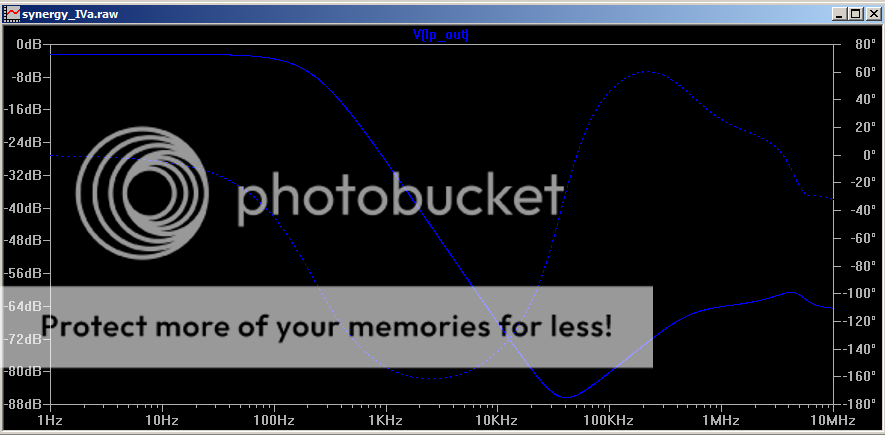
I'm still not 100% happy about the resonance at about 370Khz in the LP filter or the fact that the phase starts dropping around 20Khz, but I figured that since the crossover freq is 200Hz and the rise starts at about 30Khz and maxes out at about -60db I shouldn't be too worried. I was able to reduce the hump by reducing the cap from 100nF to 10nF but that required increasing the resistors by a factor of 10 as well which resulted in too high values. Hopefully the hump won't cause any problems as where it starts to rise will be out of the audio range. I guess I'll find out when I build it!
After all that I decided that it would probably be a good option to add some baffle step compensation. Rod Elliot has a very simple passive circuit that fits the bill nicely (see the variable equaliser). the sim shows two resistors but in reality a pot would be used unless you know exactly how much BSC you need. The resistor combo shown will give around 3db of attenuation. The value of 22nf with the resistor values of 10k and 5k (half a 10k pot) is right for a baffle width of 240mm... this is exactly half way between my MTM's (at 200mm) and the Planned baffle width of my rehoused 10" dual subs of 280mm.
So that is where I am currently. Attached is the circuit diagram and plots showing the frequency response. I will add the spice model and distortion plots a bit later (they take a really long time to compute!). I may also add a bit more info about the circuit if there is interest
A lot of the parts have been ordered, but it will be a few weeks before they are delivered due to some caps being on backorder, so it will be some time before there is a physical realization of this circuit.
so enough waffle. Here it is
11/Apr/2010. Note I have added the zip file of the spice model which has everything in it (see the readme file) you need to get this circuit simming in LTSpice. I have also created a thread in the Analog Line Level forum It also has the latest version of the schematic in it. Yes I was being optimistic in saying that the one posted was the final design
So here I present the Synergy "Active" Crossover. Please note I have only simmed it at this stage (and when I started I knew nothing about active filter design) so there is no guarantee it will work.
Why have I put "Active" in quotes? Because whilst this filter uses active components, for all intents and purposes it behaves like a passive filter. It basically emulates either an LC or a CL passive 2nd order filter.
Why the name Synergy? Well I though it was the best word to describe the differing technologies working together to give the end result
The design goal is to have an active crossover that for all intents and purposes is transparent. That is it does nothing other than split the frequencies at the desired crossover point.
For simplicities sake I went with second order and I decided on a Linkwitz Riley alignment. I had toyed with the idea of doing a Bessel alignment (due to the benefits it provides in transient response) but in the end decided that the LR was a good compromise between transient response and pass-band flatness (probably the conclusion most designers come to). edit 04/01/2011: Note that after more simulation I've changed my mind on this and will probably be going with a bessel filter, whilst a 4th order LR has superior rolloff to a 4th order bessel, a second order bessel actually has a narrower notch than a second order LR (ie less overlap of frequencies from the drives) and at the point I will be crossing a slight bump in the response will probably be advantageous.
The Job that this crossover will be fulfilling is to crossover from my 10" Woofers to my new Morel MTM's Crossover frequency is 200Hz.
From the beginning I was interested in doing this crossover a little differently. I liked the idea of using B1 buffers and was thinking of using opamps for the filter part and B1's to buffer the filter stages. I'd read about FDNR's in Walt Jungs opamp applications But they seemed a bit mystical and an unachievable goal. I thought I'd use a state variable filter, but the number of opamps seemed prohibitive. Then along came the B1 Active crossover thread. Thank You Jacques!!!
Sallen Key wasn't my preferred choice of filter, I'd looked at some online filter simulators and sallen key seemed to have some strange phase problems, but I was still interested (and it certainly fulfilled the requirement of being different!). D to the G in Post 59 quoted something from SY's Acheron web page and that essentially is the post that led me to this design.
The first generation Synergy crossover used a Gyrator circuit based on the one SY used for his Acheron. When it came to the LP I was going to use the sallen key as per Jacques' B1 design, but I was not overly happy with the simulation, so I started to look into using an FDNR. It didn't take too long to get something that looked promising in at least the AC Analysis, but a transient simulation quickly showed that the circuit oscillated! A lot of fiddling later and I discovered the cure. The Resistors in positions 2 and 5 needed to be 10X the size of the resistor in position 4. anything other than this ratio and it was guaranteed to oscillate.
The values for the components (for the FDNR in the low pass) were arrived at by using an online filter calculator and putting in a value of one ohm for the filter load impedance and the crossover freq I was interested in. I then only performed the scaling of the capacitor values from 1Farad down to 100nF.
After sorting the low pass I decided to do some fft's. What I found was that there was a big difference between the distortion on the high pass and the low pass sections. The low pass was MUCH better. about -105db compared to -96db for the high pass. At first I thought maybe it was the gyrator circuit (which I guess it was) so I decided to look for an alternative active inductor, going back to the walt jung document, I realised I could use a different relalisation of the GIC building block that the FDNR is made from to make an active inductor. This I did and whilst the distortion performance was only fractionally better than the gyrator, the phase was almost a perfect match for the Passive equivalent circuit! Not content to have higher distortion in my high pass circuit I decided to look for causes. What I found was that by increasing the value of The cap in the filter from 15nF to 33nF and the requisite dropping of the load resistor from around 27k to 12.1k the distortion dropped to around the same levels as for the low pass circuit. (the same tweak to the gyrator circuit also resulted in lower distortion).
I'm still not 100% happy about the resonance at about 370Khz in the LP filter or the fact that the phase starts dropping around 20Khz, but I figured that since the crossover freq is 200Hz and the rise starts at about 30Khz and maxes out at about -60db I shouldn't be too worried. I was able to reduce the hump by reducing the cap from 100nF to 10nF but that required increasing the resistors by a factor of 10 as well which resulted in too high values. Hopefully the hump won't cause any problems as where it starts to rise will be out of the audio range. I guess I'll find out when I build it!
After all that I decided that it would probably be a good option to add some baffle step compensation. Rod Elliot has a very simple passive circuit that fits the bill nicely (see the variable equaliser). the sim shows two resistors but in reality a pot would be used unless you know exactly how much BSC you need. The resistor combo shown will give around 3db of attenuation. The value of 22nf with the resistor values of 10k and 5k (half a 10k pot) is right for a baffle width of 240mm... this is exactly half way between my MTM's (at 200mm) and the Planned baffle width of my rehoused 10" dual subs of 280mm.
So that is where I am currently. Attached is the circuit diagram and plots showing the frequency response. I will add the spice model and distortion plots a bit later (they take a really long time to compute!). I may also add a bit more info about the circuit if there is interest
A lot of the parts have been ordered, but it will be a few weeks before they are delivered due to some caps being on backorder, so it will be some time before there is a physical realization of this circuit.
so enough waffle. Here it is
11/Apr/2010. Note I have added the zip file of the spice model which has everything in it (see the readme file) you need to get this circuit simming in LTSpice. I have also created a thread in the Analog Line Level forum It also has the latest version of the schematic in it. Yes I was being optimistic in saying that the one posted was the final design
Total Comments 12
Comments
-
 Hi,
Hi,
This is all VERY interesting - I was hoping that Sy and Co will continue to develop the Acheron Xover with the valve sound, etc, and the pcb to suit but ....
Your design seems to be just as promising and my required Xover freq of 160Hz is just a smidgen different - here's hoping it continues to develop - easy to add a valve buffer on the O/P to get the required "colour".
Curiously, I have a number of the NOS Rifa pfe216 styrene caps (33nF & 100nF) that are a bit physically big, but are very good caps and I can send some up to you to try if you'd like.
... JhPosted 6th April 2010 at 02:49 PM by jameshillj

-
... meant to add - could you do the "sim thing" for the JC style buffers with the k170/j74 fets - I'd be quite interested to see how it compares plus the estimated balance of the harmonics - Zenmod preferred them in his version of the Lightspeed.Posted 6th April 2010 at 03:06 PM by jameshillj
-
 Hi Jh, I hadn't even thought about using polystyrene caps, didn't realise you could get them that big! always think of them as being in the pf range. I was planning on using Vishay MKP-1837's.
I can do the calcs easily for the 160Hz on the high pass. Using the filter design link above and a bit of playing around with standard values for the load resistor something close looks like:
15K load
33nf cap
29.84H coil.
The only mod that should be required for the high pass section to do 160Hz LR 2nd order would be to replace R26 with a 2.94k (if you want to make it exact you could series in a 400 ohm with the 2.94k) resistor and R6 with a 15K resistor.
The low pass is a bit tricky and I'd need a bit more time to work it out (on my lunch break at the moment and almost out of time )
Also I can run a sim with SY's triode buffer if you like. I already have the model in spice. The distortion that the filter section introduces will be higher but it is primarily 2nd harmonic so when used with a valve buffer that shouldn't be a concern
I was running the transient sim for 2 seconds (saving from 1 second) which was giving me a very clean and stable fft but takes a LONG (a number of hours) time on my old athlon 2000 machine. I need to play around a bit and find something that gives good results without taking an age, maybe something in the 100 - 200 ms range might be ok.. another thing that might drop the simulation time is dropping back to one of the other opa2604 models (the one I'm using is much more complex, but shows the oscilation problems when the other two don't) but now I have that sorted they may be fine for doing the transient analysis.
The distortion is around -103db 2nd harmonic and I think from memory about -138db 3rd harmonic. (figures are a bit better without the BSC circuit but only marginally). higher harmonics are from memory a lot lower.
Give me a link to the JC style buffers and I'll see what I can do I do intend to upload the spice circuit and all of the additional models/subcircuits necessary to run the sim too. I might also start a thread seeing there is some interest probably in the analog line level forum.
cheers,
Tony.Posted 7th April 2010 at 03:58 AM by wintermute
-
A'noon Tony,
I haven't had time to go deeper into your cct so some of my comments are probably rubbish, but first I'll show my ignorance - can you add the link to Walt Jungs place where your alternative to the gyrator cct comes from - I take it this is the FDNR? I guess i'd better figure out how these things actually work instead of just talking about it!
The Rifa styrene caps are physically 29mm long, 8.5wide and about 9.5 high with 30mm legs at 25mm spacing - these are the new old stock from years ago when they used to make them here - excellent sound - those 1837 are the ones that the "Humble Homemade" guy is very keen on as bipass caps - I've got some of the 15nF value - tiny little blue things? Apparently they sound pretty good too.
Sy's Acheron and the heretical buffer - this is the same one that appeared on the Cavalli audio design pages, yes? Needs the high volts plus -20 volt (dc o/p - no o/p cap) plus a +/- 12v for the servo chip - quite a bit of stuff! - less than 200R o/p impedance, tho.
It would be quite interesting to see what variations are available with this valve buffer - it's been around for a bit but not any body built it yet.
Can the input Z to your Xover be increased to 100kR - I'm keen on using the Lightspeed as a main volume control and it works best with a high input load - at the other end, my First Watt F3 amp (for the high pass) only has a 9kR input Z (the First watt F3) so the high pass filter buffer o/p may need some attention. Incidently, is there a volume adjustment on the low pass o/p and would it need another simple buffer or perhaps a gain stage like the BF862 cct?
Not much of an IC person - can i sub a 2134 for the 2604?
Good bit of detail work picking up on the 2604 doing it's "song and dance" routine - bet that would have added an edge to the sound!
The easiest place for the JC buffers (k170 & j74 jfets) is Zenmod's "Poor Serbian Man's Lightspeed" - I still can't make the attachment thing here work - might get your email address and PM the info directly.
Had a brief look at your regulator cct - looks okay - about Salas' shunt cct, the basic design actually has no problems with reasonably length supply leads and has a remarkable sound and will be just fine for multiple buffer stages altho perhaps provision for some local decoupling may/maynot be a pcb idea - it's the newer remote sense design (and also Iko's) that needs short coupling leads. I'm a bit nutty about the sound of the power supply and have been playing around with John Brown's (from EC Design) idea of using triple diode rectifiers to reduce diode noise - works like a charm (3 diodes, 2 resistors) - also trying out idea about not using electros for the ripple reduction or supply - not new idea by any means but I've not managed to try it out - now's agood time!
I might be able to help with some pcb design - It's like Sudoku for me - only have prehistoric Protel package but it works okay for me and it's the quality of thinking that's more important, IMO!
Might be interesting to see if anyone on the main B1 Xover thread actually gets around to doing a design that doesn't include all the options in the book!
I think SY is working with Pete Millet (headamp guy) but I think it might take awhile as both pretty busy.
I'll send a PM.
... JamesPosted 7th April 2010 at 05:46 AM by jameshillj
-
Hi James the link to the specific chapter is in the blog entry (just click on Walt Jungs Opamp Applications) Analog Devices have the whole book available for download and Walt Jung also has it I think + lots of other goodies on his site link here.
Those rifa caps sound BIG! I think I'll stick to the MKP's though I did notice PartsConexion have 33nf styrene caps for 50c each. I might order a matched pair along with my other stuff just to try them out no idea what size they are though!!
I don't see any reason why the input to the first buffer can't be increased to 100K I asked the question in the pass labs forum because I wasn't sure if having megaohm values on the input would be a problem and Zen Mod said it should be fine
I'd been contemplating how to deal with volume control for the individual sections. That could be a problem. Without the baffle step circuit I think pots after the initial buffer on the input buffer for each of the low and high pass sections could possibly be an option. According to Rod Elliot, it needs a high load impedance of at least 100k, the higher the better, so maybe a 100k trimpot could work there. Otherwise another buffer stage might be necessary, I don't know whether you could put a pot on the output... I'd have to look at a few other cirucits to see whether it is a bad idea or not Certainly it would be a bad idea to put a pot in the place of the 12.1K resistor in the high pass, or the 10Mohm resistor in the low pass as (especially in the high pass) this resistance has a big bearing on the corner freq of the crossover. Actually from memory I think in the LP it doesn't affect the freq at all, but if it is too low then there is a big insertion loss.
On the question of the 2134 for the low pass I'd say NO. I haven't tried it in the high pass. The original gyrator circuit I was using the opa134 and it was fine (changing to the 604 made no difference. But the 134 in the sim performs very poorly in the FDNR circuit. The 2064 is actually a compromise in itself. I wanted to use as low a bandwidth opamp as possible to limit the potential problems, but the 134 didn't cut it. I actually simmed with a LOT of opamps (probably close to 50) and not many worked well. The LT1022 works quite nicely (quite a bit better at high frequencies than the opa2604) but it is expensive, has a nasty dip at around 17KHz, and not available (that I can find) in a dual package. Also I don't know how much is down to the model, and how much down to the actual device, but I guess I tried a lot of Linear Tech opamps (because they come with LTSpice) and most of them didn't cut it. I tried to work out what specs the ones that were good had that were different to the ones that weren't but I couldn't find anything consistent. I think though at least 14Mhz of bandwidth and a reasonably high slew rate seem to be a requirement.
On the power supply, I am actually planning on having local decoupling. 1000uf silmics for the first stage then for each of the low pass and high pass sections, all separated from the main supply with 1 ohm resistors ala Nelson's original B1. Probably overkill, but in the sim it reduces the ripple to next to nothing (about 2uv at 150Ma current I think). I've also ordered a bunch of 1uf Axon polypropylene caps, but I may not actually use those.
I haven't started to try and do a layout yet, but I was planning on doing it on verro board! I've never designed a pcb before. So if you feel the urge to design a pcb go for it
Yes SY is busy! I've asked him a few tricky questions some of which he has been able to answer but some need some investigation which he hasn't the time for at the moment. Oh and as far as I am aware SY himself has built the acheron and I assume the buffer as well.
Cheers,
Tony.Posted 7th April 2010 at 08:20 AM by wintermute
-
Hi James, just ran a sim and there is NO difference between the opa2604 and an opa134 in the high pass section. So I might actually drop back to the 134 for the high pass as it is a lower risk proposition as far as running into trouble. The difference in the low pass is not as big as I thought. This may be due to the changes I had to make to stop it from oscillating. The other opamp I was thinking about was the LT1122 not the LT1022. Funnily enough the opa2604 is the closest match to the ideal passive realisation out to 20Khz. Below is the image (assuming I can post an image link in a comment).
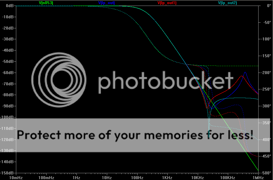
Green trace, ideal passive inductor/capacitor
Blue trace opa2604
red trace opa134
turquoise trace LT1122
Cheers,
Tony.Posted 7th April 2010 at 09:35 AM by wintermute
Updated 7th April 2010 at 01:59 PM by wintermute -
Thanks Tony,
Okay, I got the info from Walt's site and will have to go back to school and relearn (if I ever got it right originally!) about all these things
!
Also, got the message about the difference between a FDNR and a GIC.
For anyone else mystified by this shorthand gobbledegook, GIC means "General Impedance Convertor" and the FDNRs are "Freq dependent Negative Resistors" and are different to "Gyrators" which aren't actually "Cmultipliers" at all.
If you're like me and not very conversant with these particular ccts, you'll just have to look them up, too!
... will now go and study the basics.Posted 8th April 2010 at 12:14 AM by jameshillj
-
Cheers James, I should revise the main blog entry to clarify some of this stuff! I've been so immersed in it lately I forget that when I first started looking at it how foreign it all was!
Tony.Posted 8th April 2010 at 03:17 AM by wintermute
-
Ah Tony,
I went back over your original first post and all the info about your design IS contained in it - i just didn't understand what I was looking at!
The cruz of the difference to SY's cct is the GIC instead of the Gyrator for the HP and another (matching) GIC instead of the S/Key feedback filter for the bass, or LP.
Then all we need do is get the hang of this "GIC thing", as the rest of the cct is standard B1 Xover.
The only other difference appears to be your choice of the LR, rather than the Butterworth style filters.
With the input Z now up near the 100kR mark, this will match up to the Lightspeed Vol control quite well.Posted 8th April 2010 at 08:03 AM by jameshillj
-
Hi James, I worked through the calculations for the FDNR tonight with your 160Hz crossover freqency. Please see below the scan of the calculations. I figured this might be useful to anyone who wants to work out their own filter. I started by using the filter calculator linked to in the blog entry putting in an impedance of 1 ohm and freq of 160Hz to arrive at the values for L and C of 1.98937mH and 497.5uF. I show the transformation to values for the FNDR circuit in the graphic below:
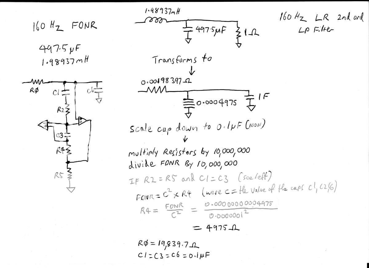
Note that if you don't want to do the calculations you can simply take the value of the inductor in mH and shift the decimal place one place to the right to get your resistor value for R0 in K , and take the value of the cap in uF and shift the decimal place 1 place to the right to get your R4 value in ohms. (this is if you use 100nf caps).
R2 and R5 have to be equal (for the above simplified calculation), and theoretically can be any value, but I had problems with oscillation in the sim unless they were at least 10 times the value of R4.
resulting curves blue the FDNR circuit, green the passive, show below:
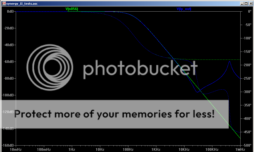
Obviously I haven't changed the resistors to standard values. but that can be done, and a little tweaking up and down of the R0 and R4 values can result in an almost perfect match to the theoretical filter response.
Cheers,
Tony.Posted 8th April 2010 at 12:31 PM by wintermute
Updated 8th April 2010 at 06:49 PM by wintermute -
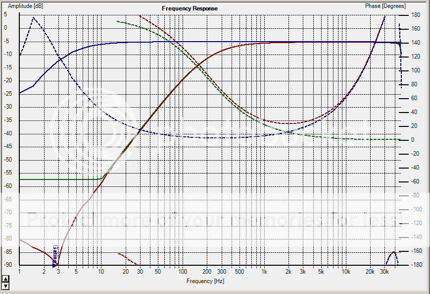
I thought I'd post an update via the comments I finally breadboarded the highpass part of the circuit and tested, and I'm happy to report that it works!!!
The resistors used were for a 2nd order L/R crossover at 200Hz. Below is a target response (orange) generated in PCD, compared to the actual measured response of the crossover (red). The Blue is the loopback response of the soundcard to show that the weird phase behaviour is actually the card and not the crossover (my holm is playing up and I can't currently calibrate it).
Note that I didn't have the exact resistor values I needed, so have compromised a bit for this prototype but it is still very close.
I've also managed to improve the LP in the sim, smoothing out the dip and rise after 20Khz. The solution was to put a 220pf cap across one of the resistors in the FDNR. I'm not sure why it works but it seems to help.
So for anyone who has wondered, I am still working on this, I'm just making very slow progress. However I would like to have the completed circuit done (on a board not breadboard) by the end of March, so stay tuned.
Tony.Posted 29th January 2012 at 12:15 AM by wintermute
-
Well I guess I should make an update regarding the FDNR on the lowpass. It's not working as well as I had hoped. It is basically oscillating, and I haven't found a solution as yet. I think I need to read up on Open Loop gain and phase margins to get my head around the problem and work out whether it is something that is fixable or whether it is simply not suitable for a crossover frequency this low.
Tony.Posted 6th February 2012 at 12:07 PM by wintermute

