Go Back   Home > Forums > Blogs

Old

Discrete Op Amp measurements

Posted 12th June 2017 at 06:25 AM by googlyone
Updated 12th June 2017 at 06:30 AM by googlyone (errors!)

I finally got around to doing some measurements on the discrete op amp at G=2 and G=10.

These were non inverting mode - note the voltage was 6-8V p-p, and the rails were +/-15V so there was a fair whack of headroom. Anyway, I will let the measurements speak for themselves.

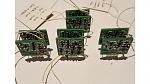
This is what they looked like...Click image for larger version

Name:	complete devices.jpg
Views:	91
Size:	712.2 KB
ID:	2414


I tested a whole bunch of configurations of the DOA, including:

Differential pair current 1, 1.5, 2 and 4mA
Output current 8mA (2* 4mA) and 12mA
VAS current 1.5, 3mA.

The test setup was a dual op amp board, one channel set to G=2 the second set to G=10.

The load for G=2 was 1kOhm. The load on G=10 was 10kOhm. I could go back and retest this... I had not lingered on this during the test.

The first challenge I found was MASSES of noise really messing with the results. It looked a lot like oscillation, and I kid you not, I spent hours trying...
Attached Thumbnails
Click image for larger version

Name:	G10-Idiff2mA-CM470p-iOP8mA-11kHz_FFT.jpg
Views:	54
Size:	386.9 KB
ID:	2405   Click image for larger version

Name:	G1-Idiff2mA-CM470p-iOP8mA.jpg
Views:	36
Size:	310.1 KB
ID:	2406   Click image for larger version

Name:	G1-Idiff2mA-CM470p-iOP8mA-50KHzCut.jpg
Views:	14
Size:	309.1 KB
ID:	2407   Click image for larger version

Name:	G1-Idiff2mA-CM470p-iOP12mA-nocro.jpg
Views:	16
Size:	309.7 KB
ID:	2408   Click image for larger version

Name:	G10-Idiff1mA-CM470p-iOP8mA-60kHzLP.jpg
Views:	19
Size:	311.8 KB
ID:	2409  

Click image for larger version

Name:	G10-Idiff2mA-CM470p-iOP8mA.jpg
Views:	19
Size:	313.1 KB
ID:	2410   Click image for larger version

Name:	G10-Idiff2mA-CM470p-iOP12mA-nocro.jpg
Views:	15
Size:	313.5 KB
ID:	2411   Click image for larger version

Name:	G10-Idiff4mA-CM220p-iOP8mA.jpg
Views:	18
Size:	312.4 KB
ID:	2412   Click image for larger version

Name:	G1-Idiff2mA-CM470p-iOP8mA-FFT.jpg
Views:	31
Size:	402.3 KB
ID:	2413  
diyAudio Member
Posted in Uncategorized
Views 255 Comments 1 googlyone is offline
Old

Discrete Op Amp PCB Build

Posted 25th May 2017 at 10:18 PM by googlyone

Well I am home again, and the PCBs for the discrete op amp beat me home.

I used PCBcart, who have a very competitive prototype PCB service -it is certainly not worth your time to make fiddly double sided boards like these at home!

They came out like this...

Click image for larger version

Name:	finger.jpg
Views:	176
Size:	621.2 KB
ID:	2397

And no, I don't have a finger the size of a baguette...

More images to give you some scale of these little buggers:

Click image for larger version

Name:	horizontal.jpg
Views:	106
Size:	782.1 KB
ID:	2394

Click image for larger version

Name:	both.jpg
Views:	79
Size:	636.5 KB
ID:	2395

and thru the microscope which I had to use to solder the bits on:

Click image for larger version

Name:	microscope.jpg
Views:	101
Size:	1,000.2 KB
ID:	2396

There are parts on both sides of these PCBs.

A this point I am yet to mount the miller cap, as I want to play with this a bit. On the schematics there is a "guaranteed to work" value. I want to measure the phase margin and stability into some odd loads - as overcooking this will directly affect...
diyAudio Member
Posted in Uncategorized
Views 327 Comments 4 googlyone is offline
Old

Discrete OpAmp - Replaces Dual Channel DIP8 - design and PCB

Posted 11th May 2017 at 06:28 PM by googlyone

Well here I am travelling again, and this time stuck for an extra week away from home. The design bug has bit, and this time I tried keeping things small rather than crazy.

I have built a number of discrete operational amplifiers in the past. Usually integrating everything onto the board so that they wind up being preamplifiers rather than operational amplifiers.

If that confuses you - the difference is that an operational amplifier needs to be plugged into a circuit to be useful, a preamp is a standalone PCB.

The inspiration was seeing a burson amp on ebay. I looked and thought to myself "I keep starting that, and keep ending up with a preamp". Then I thought "Do it right for once".

The resultant goals:
- Dual channel op amp
- DIP8 pinout
- Good perfromance
- Class A (vs class AB which many are)
- Minimum size, whilst
- Sticking to 0805 SMD resistors caps, and...
Attached Thumbnails
Click image for larger version

Name:	Board1.jpg
Views:	99
Size:	424.7 KB
ID:	2386   Click image for larger version

Name:	Board 2.jpg
Views:	75
Size:	473.9 KB
ID:	2387  
Attached Files
File Type: pdf Composite CH1.pdf (11.6 KB, 82 views)
File Type: pdf Composite CH2.pdf (13.5 KB, 53 views)
File Type: pdf Schematic CH1.pdf (24.6 KB, 141 views)
File Type: pdf Schematic CH2.pdf (24.8 KB, 86 views)
File Type: pdf Final Artwork CH1.pdf (21.2 KB, 65 views)
File Type: pdf Final Artwork CH2.pdf (22.9 KB, 49 views)
diyAudio Member
Posted in Uncategorized
Views 301 Comments 0 googlyone is offline
Old

Now For Something Completely Different - In a Neat Little Box!

Posted 22nd April 2017 at 04:30 AM by googlyone
Updated 22nd April 2017 at 04:40 AM by googlyone

After a few months of playing with loudspeaker drivers and software fixes to code that I wished I had never written in the first place, the lure of the BJT loomed large again...

There I was, sitting at my desk, and pondering where these dark feelings were coming from and how to scratch that evil itch, and my eyes came to rest upon that most ludicrous of things - the amplifier of 100 transistors.

About a year ago, or so it seems to me sitting here, I built this homage to the BC549, or as the engineer in me says, "Laughably stupid thing, which probably shouldn't work. Who would be dumb enough to try and find out?".

It needed a case. It needed a power supply. It deserved each of the above that would allow it to work, and ideally take an equally "left field" approach. it should never have been built, but it had. It should have been put in the back of a very dark, locked cupboard, but it had not.

The idea then...
Attached Thumbnails
Click image for larger version

Name:	RESIZE_Many_Tiny_Chassis.jpg
Views:	104
Size:	734.6 KB
ID:	2354   Click image for larger version

Name:	resize_MAny_Tiny_Workshop.jpg
Views:	123
Size:	973.2 KB
ID:	2355   Click image for larger version

Name:	resize_Many_Timy_Complete.jpg
Views:	218
Size:	1,010.2 KB
ID:	2356   Click image for larger version

Name:	RESIZE_Many_Tiny_Chassis_1.jpg
Views:	119
Size:	974.4 KB
ID:	2357   Click image for larger version

Name:	Resize_Many_Tiny__Case.jpg
Views:	114
Size:	848.1 KB
ID:	2358  

Click image for larger version

Name:	Resize_Many_Tiny_Lid.jpg
Views:	93
Size:	956.8 KB
ID:	2359  
Attached Files
diyAudio Member
Posted in Uncategorized
Views 445 Comments 4 googlyone is offline
Old

Richard Allan CG10 Find - Some "New-Old-toys"

Posted 21st March 2017 at 11:49 AM by googlyone

Years ago I moved from the country back into the city. This was a move that required me to clean out heaps of stuff that I really didn't want to clear out. In our old place we had two houses on the block, one of which had been converted into an enormous studio room with NO walls, and a 14 by 14 metre shed. To say that I amassed a collection of speakers and stuff would be an understatement.

One of the things I got rid of were a pair of Richard Allan CG-10 drivers that I never got around to sticking in a box. Indeed, I never even got around to measuring their parameters.

Recently on EBAY I came across a pair of these...

Click image for larger version

Name:	Richard_Allan_CG10_Front_View.jpg
Views:	171
Size:	829.2 KB
ID:	2323


Click image for larger version

Name:	Richard_Allan_CG10_Rear_View.jpg
Views:	162
Size:	974.0 KB
ID:	2324

I was surprised at the condition of these - the cones look new. Needless to say they are not, the date code is 1973.

I have measured and used the CG-12, HD-15 and a bunch of other Richard Allan drivers in the past and found them...
diyAudio Member
Posted in Uncategorized
Views 419 Comments 0 googlyone is offline
Old

Did I REALLY do that?

Posted 12th March 2017 at 04:49 PM by googlyone

in my electronics workshop I have always had a stereo. Eight years ago I looked on the shelf and decided there was all the makings of an integrated preamp - DSP - Crossover and four power amplifiers.

That is the price of always making an extra board or two when I build a "thing" - you end up with a massive collection of bits.

I duly shoe-horned this lot into a case that is about 3" high. Tuned it up and didn't think a lot more.

Fast forward 8 years to two weeks ago, and there I was listening to the radio while wondering what to build next, and I thought the left tweeter sounded a bit low.

I swapped input to the amp L-R, and yep, it was. Odd - as the DSP treats L and R exactly the same, there is no balance control in there. So I swapped the speakers. Hmm, it wasn't the tweeter. It was inside the "box".

So I popped the lid, and found this...

Click image for larger version

Name:	DSP_XO_AMP.jpg
Views:	311
Size:	1.05 MB
ID:	2322
...
diyAudio Member
Posted in Uncategorized
Views 459 Comments 0 googlyone is offline
Old

Discrete Operational Amplifier - Open Source (SMD)

Posted 8th January 2017 at 02:35 AM by googlyone
Updated 8th January 2017 at 02:49 AM by googlyone

Well here I am at the end of another summer holiday - with yet another thing I have built for which I have absolutely no plans at all!

I have over the years built several (several dozen I would expect!) discrete operational amplifiers. The challenge I set myself here was:
- Actually get some proper measurements of it's performance, now that I have some test gear that is up to the job.
- Make the device in something close to a DIL-8 package. (slight fail here but close enough)
- Discrete
- Use some of the multitude of parts I have collected of late.
- The ability to configure the op amp as a buffer or amplifier with non-inverting gain. This means adding feedback resistors and a DC block cap.
- The ability to include input RF filter (typical few hundred ohms series and 1nF across the input)

The schematic won't surprise anyone - over the years I have designed ridiculously complex and simple amplifiers, and have run...
Attached Thumbnails
Click image for larger version

Name:	SMD Opamp Composite.png
Views:	212
Size:	141.9 KB
ID:	2219   Click image for larger version

Name:	20161230_134736-resized.jpg
Views:	299
Size:	533.0 KB
ID:	2220   Click image for larger version

Name:	20161230_171403-resized.jpg
Views:	183
Size:	281.3 KB
ID:	2221   Click image for larger version

Name:	1khz Loopback Distortion Test 2vp-p.jpg
Views:	150
Size:	418.8 KB
ID:	2222   Click image for larger version

Name:	1khz output meas 2vp-p.jpg
Views:	107
Size:	425.1 KB
ID:	2223  

Click image for larger version

Name:	1kHz 2vp-p A=11.jpg
Views:	117
Size:	428.2 KB
ID:	2224   Click image for larger version

Name:	20-20kHz A=11.jpg
Views:	128
Size:	300.5 KB
ID:	2225  
Attached Files
File Type: pdf SMP Opamp Silkscreen.pdf (18.7 KB, 90 views)
File Type: pdf SMD OpAmp Top layer.pdf (18.7 KB, 114 views)
File Type: pdf SMD Opamp Schematic.pdf (114.4 KB, 229 views)
diyAudio Member
Posted in Uncategorized
Views 560 Comments 0 googlyone is offline
Old

Surprisingly Good Performance - The Amplifier of 100 Transistors

Posted 4th June 2016 at 04:42 AM by googlyone
Updated 4th June 2016 at 05:18 AM by googlyone

I finally got around to rolling out the distortion test set and the Amplifier of 100 Transistors to measure its performance.

I would like to say that I don't care - and that the whole thing is an engineering abortion. A complicated joke, and that the measurements don''t matter. The fact that I am making the measurement would however show me to be a liar - as if I didn't care, then why did I do this?

Anyway, with low distortion measurements, getting your head around the baseline of your test gear is key. With all gains / levels being equal, here is the loop-back distortion of the test system:

Click image for larger version

Name:	Final_TestSetup_Lopback_with_Divider.jpg
Views:	216
Size:	258.5 KB
ID:	1984

Which is fine, rolls along at about 0.0003% across the band.

Then I ran a sweep of the Amplifier of 100 Transistors with NO load at 3dB below clipping:

Click image for larger version

Name:	Final -3dbNoLoad_distortion.jpg
Views:	182
Size:	260.5 KB
ID:	1985

OK, this is saying the amplifier distortion raises it's head above the noise floor at 1KHz and is...
Attached Thumbnails
Click image for larger version

Name:	Final -3db8r_NICHROME WIRE WOUND.jpg
Views:	127
Size:	261.9 KB
ID:	1986   Click image for larger version

Name:	Final -3db4r_NICHROME WIRE WOUND.jpg
Views:	102
Size:	261.7 KB
ID:	1987   Click image for larger version

Name:	Final -3db8r_25W_WW.jpg
Views:	124
Size:	257.9 KB
ID:	1988   Click image for larger version

Name:	Final -3db6r_25W_WW.jpg
Views:	91
Size:	259.6 KB
ID:	1989   Click image for larger version

Name:	Final -3db3r_25W_WW.jpg
Views:	98
Size:	259.8 KB
ID:	1990  

Attached Files
diyAudio Member
Posted in Uncategorized
Views 1084 Comments 2 googlyone is offline
Old

And then there were two... Amps of 100 Transistors

Posted 28th May 2016 at 06:39 AM by googlyone

And then there were two! A lot easier simply loading just the "output devices" and testing.

The second one initially looked super stable, but after I got it quite warm by running an almost clipping sinewave into a 4 Ohm load, I did find just a tough of oscillation on negative excursions.

The first amp had envelopes of oscillation at 3MHz. The frequency of the second amps oscillation was 13MHz.

In the end removing the capcitor between the bases of the output devices (what was it there for anyway?) tidied things up.

These Amplifiers of 100 Transistors seem to breed!

Click image for larger version

Name:	DSC05252-smaller.jpg
Views:	437
Size:	937.3 KB
ID:	1983
diyAudio Member
Posted in Uncategorized
Views 720 Comments 2 googlyone is offline
Old

The Amplifier of 100 Transistors (output devices)

Posted 28th May 2016 at 02:18 AM by googlyone
Updated 28th May 2016 at 02:22 AM by googlyone

In my previous post I presented an idea spawned from a very bad place, primarily boredom and probably too much alcohol. Plane trips from Australia do that...

The Amplifier of 100 Transistors was the result.

Between that posting and this a few things have happened. I finished the design - adding extra decoupling and 100 Ohm base resistors to all 104 output devices. I did this because I sincerely thought I was building more of an RF oscillator than amplifier.

And I built it.

And I got it working.

This is the beast from the back before I loaded the "output devices":

Click image for larger version

Name:	DSC05235_smaller.jpg
Views:	399
Size:	875.2 KB
ID:	1980

Note the ludicrous number of emitter and base resistors! Half way through I concluded that I was bonkers, and wasting several days hand building a complete folly.

Then again, even with the thing running, it is still a folly!


With the output devices loaded....
Attached Thumbnails
Click image for larger version

Name:	DSC05249-smaller.jpg
Views:	262
Size:	975.5 KB
ID:	1981   Click image for larger version

Name:	DSC05251-smaller.jpg
Views:	335
Size:	985.7 KB
ID:	1982  
Attached Files
diyAudio Member
Posted in Uncategorized
Views 787 Comments 1 googlyone is offline

New To Site? Need Help?
Copyright ©1999-2017 diyAudio